Preface
With the continuous advancement of industrial automation, intelligent manufacturing and energy-saving control technologies, Frequency Converters (VFDs) have become an indispensable core piece of equipment in modern industrial electrical control systems. Widely applied to fans, water pumps, air compressors, conveying equipment, HVAC systems, CNC machine tools, packaging machinery and automated production lines, frequency converters undertake key functions including motor speed regulation, energy consumption optimization and equipment operating efficiency improvement.
Compared with traditional power-frequency driving modes, frequency converters can adjust output frequency and voltage in real time according to actual load demands, realizing soft motor startup, stepless speed regulation, constant pressure control and precise speed adjustment. They not only mitigate the impact of large startup current on power grids, but also effectively reduce mechanical wear, extend equipment service life, and help enterprises cut energy consumption and operating costs.
Nevertheless, frequency converters generally operate in harsh industrial environments featuring high temperature, high humidity, heavy dust and intense vibration. Meanwhile, their stable operation is affected by various factors such as power supply quality, load fluctuations, wiring modes, parameter configuration and on-site electromagnetic interference. During long-term operation, equipment failures including startup failure, overcurrent alarm, overvoltage protection, overheating shutdown, abnormal output and communication faults may occur. Failure to diagnose and resolve faults in a timely manner will not only disrupt stable equipment operation, but also trigger full production line shutdowns, raising corporate maintenance costs and production losses.
It is worth noting that on-site statistics show most frequency converter failures do not stem from damaged core power devices, but are closely related to improper installation and commissioning, incorrect parameter configuration, poor environmental conditions or inadequate daily maintenance. Therefore, establishing standardized scientific fault diagnosis procedures and formulating comprehensive preventive maintenance plans is critical to boosting equipment reliability and reducing unplanned downtime.
Combined with typical industrial application cases, this paper systematically analyzes the most frequent faults encountered during frequency converter operation, elaborates typical fault causes, standardized troubleshooting procedures, solutions and daily maintenance recommendations. It helps equipment maintenance technicians, engineers and system integrators quickly locate faults, and enhances the safety, stability and service life of equipment.
What Are the Most Common Faults of Frequency Converters?
Despite differences in hardware structure, control algorithms and functional configurations among frequency converters of various brands and series, fault types share high commonality based on industrial on-site maintenance experience. Understanding these typical faults and their manifestations is the first step to improving fault diagnosis efficiency.
| Common Faults |
Typical Manifestations |
Possible Impacts |
| Failure to start |
No display after power-on, no output, motor not rotating |
Equipment shutdown |
| Overcurrent fault |
Frequent tripping during startup or operation |
Abnormal motor operation |
| Overvoltage fault |
Alarm triggered during deceleration or shutdown |
Deteriorated braking performance |
| Overheat protection |
Temperature alarm, automatic shutdown |
Shortened service life of components |
| Abnormal output |
Fluctuating voltage/frequency, motor jitter |
Unstable processing performance |
| Communication fault |
Failed PLC communication, abnormal data |
Interruption of automatic system |
| Display abnormality |
Black screen, garbled codes, unresponsive buttons |
Inability to monitor equipment status |
| Abnormal noise |
Increased fan, electromagnetic or mechanical noise |
Potential underlying faults may exist |
It should be emphasized that identical alarm codes do not always correspond to identical fault causes. For instance, an overcurrent alarm may result from motor short circuits, overly short acceleration time, sudden load changes or unreasonable parameter settings. Hence, maintenance personnel must not judge faults solely based on alarm information; comprehensive analysis combining operating environment, historical records and on-site working conditions is required.
During actual maintenance and inspection, it is recommended to follow the principle of "power supply first, control circuit second; external components first, internal components second; software first, hardware second" to gradually narrow down the fault scope. Standardized troubleshooting procedures can greatly boost maintenance efficiency and avoid misjudgment and unnecessary component replacement.
Troubleshooting Frequency Converter Startup Failure
Frequency converter startup failure is one of the most prevalent faults at industrial sites and the top priority for maintenance technicians to address. A non-startable frequency converter not only renders motors inoperable, but may also shut down entire production lines, reducing production efficiency and equipment utilization. Accordingly, blind equipment disassembly should be avoided during maintenance; instead, systematic and scientific fault diagnosis procedures shall be adopted to analyze fault sources step by step.
Generally, frequency converter startup failure manifests in the following scenarios:
- No display on the screen after power supply is switched on
- Power indicator light remains off
- Normal display yet no response to startup commands
- No motor output or abnormal output voltage
- Instant activation of protection mode upon startup
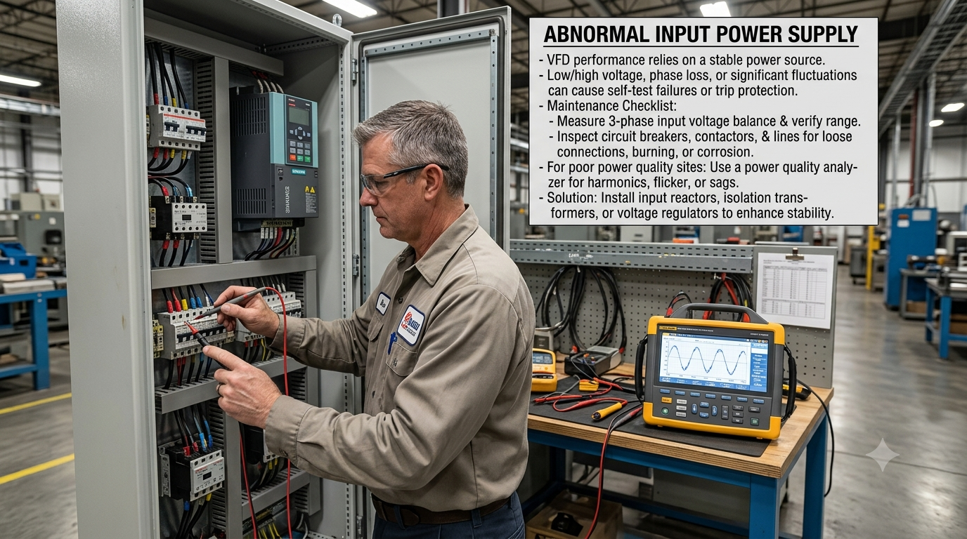
1. Abnormal Input Power Supply
A stable power supply is the foundation for normal frequency converter operation. Excessively low or high input voltage, phase loss or severe power fluctuations may prevent equipment from completing self-inspection procedures or directly trigger protection mode.
Maintenance personnel shall first measure three-phase input voltage balance and verify whether the actual voltage falls within the equipment’s allowable operating range. Meanwhile, inspect circuit breakers, contactors and power supply lines for loose connections, ablation and oxidation.
For industrial sites with poor power supply quality, a power quality analyzer may be used to detect harmonics, voltage flicker or instantaneous voltage drops. If necessary, input reactors, isolation transformers or voltage regulators shall be installed to improve system stability.
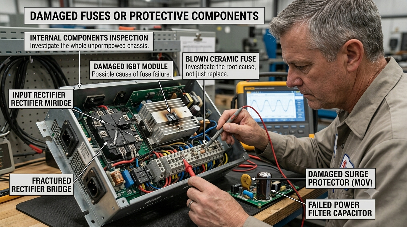
2. Blown Fuses or Damaged Protective Components
If input power supply is normal yet the equipment remains completely unresponsive, further inspection of internal fuses and protective components is required.
Blown fuses usually indicate prior system short circuits, large current surges or abnormal power devices. Maintenance personnel shall not simply replace fuses; the root cause of blowing must be identified first. For example, damaged input rectifier bridges, breakdown IGBT modules or output short circuits may cause repeated fuse blowouts.
Additionally, check surge protectors, varistors and power filters for obvious scorching, bulging or discoloration. Though small in size, these components directly guarantee the overall power supply safety of the equipment.
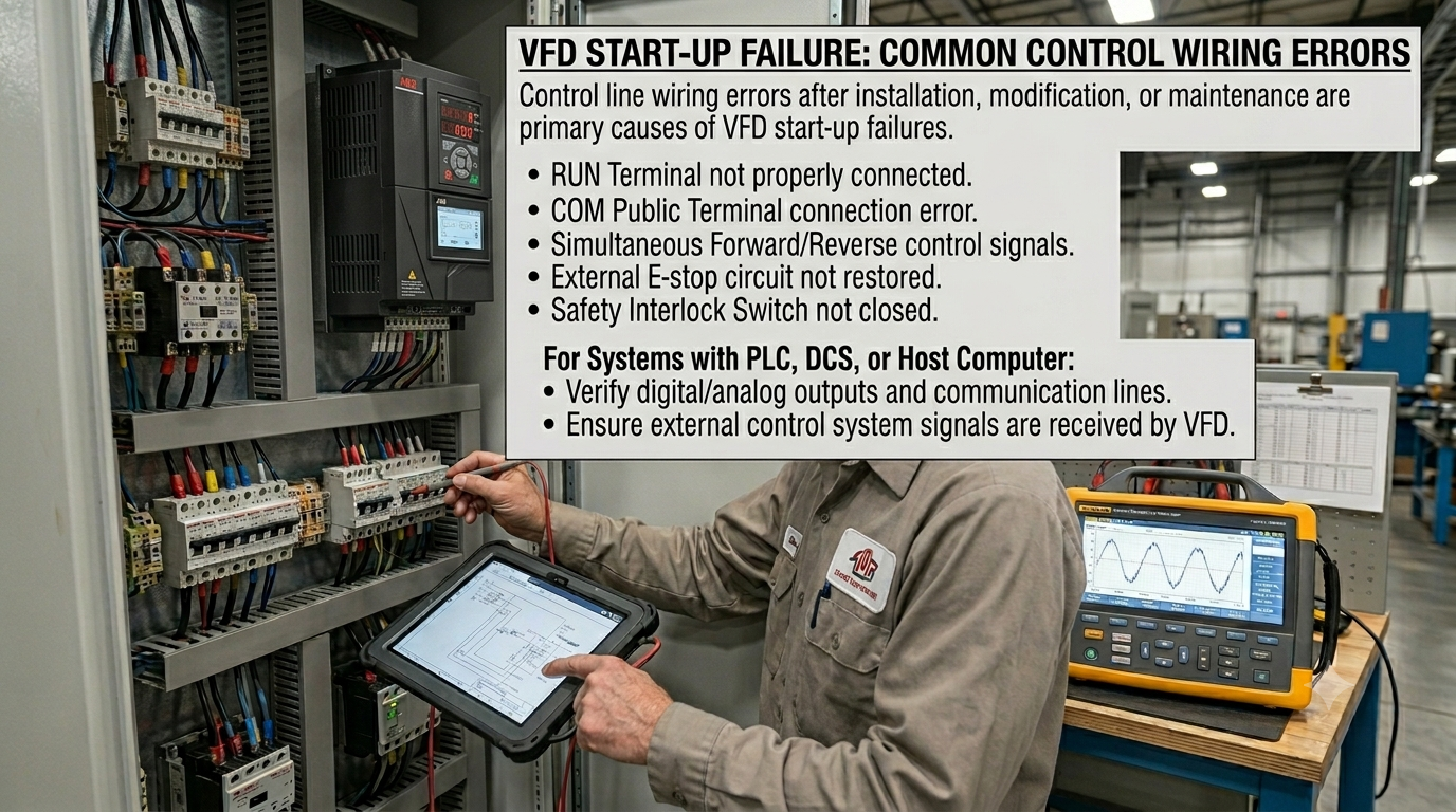
3. Incorrect Control Circuit Wiring
Incorrect control circuit wiring after new equipment installation, system renovation or equipment maintenance is a major trigger of startup failure. Typical wiring errors include:
- Improper connection of RUN terminals
- Misconnection of COM common terminals
- Simultaneous input of forward and reverse rotation control signals
- Unrestored external emergency stop circuit
- Unclosed safety interlock switches
For systems controlled by PLC, DCS or upper computers, confirm that digital outputs, analog signals and communication lines function properly to rule out startup command reception failures caused by external control system malfunctions.
4. Incorrect Parameter Configuration
Modern frequency converters feature hundreds of adjustable parameters covering operating modes, frequency sources, control modes, protection functions and communication settings. Even with intact hardware, incorrect configuration of key parameters will render equipment inoperable.
Focus on verifying the following critical parameters:
- Correct setup of operation command source
- Frequency reference mode matching on-site requirements
- Accurate input of motor rated parameters
- Reasonable acceleration and deceleration time settings
- Activation status of special functions including PID control and multi-speed operation
For newly commissioned equipment or units with disordered parameters, back up original parameters before restoring factory defaults, then reconfigure parameters in accordance with actual working conditions.
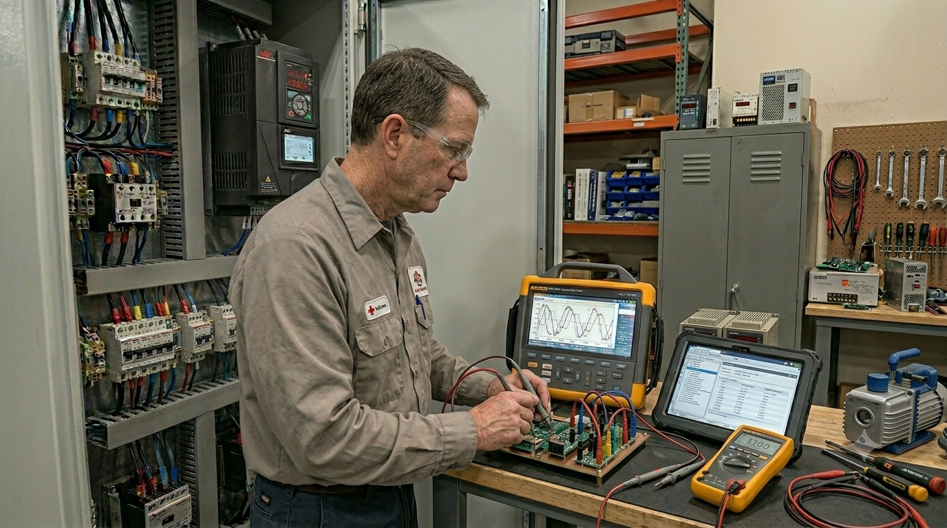
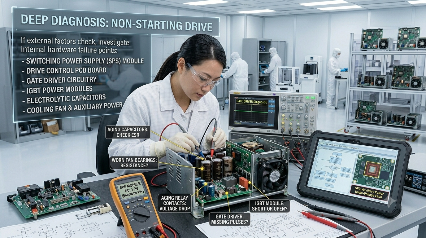
5. Internal Hardware Malfunctions
If all above items are verified normal yet the equipment still fails to start, internal hardware inspection is required. Key components to examine include:
- Switching power supply modules
- Main control PCB boards
- Drive circuits
- IGBT power modules
- Electrolytic capacitors
- Cooling fans and auxiliary power supplies
For equipment running continuously for long periods, prioritize checking aging electrolytic capacitors, worn fan bearings and aged relay contacts. Performance degradation of these vulnerable parts directly impairs frequency converter startup reliability.
Engineer Recommendations
Many on-site maintenance technicians tend to immediately replace control boards or power modules upon detecting faults. This practice not only incurs high costs but also overlooks the root cause of failures.
A more scientific standardized diagnosis workflow is as follows: first confirm normal power supply; second inspect control wiring and parameter configuration; third analyze alarm logs and historical operating data; finally conduct internal hardware testing. Adopting an outside-in, simple-to-complex troubleshooting approach enables fast fault localization while effectively lowering misjudgment rates and maintenance costs.
Causes of Overcurrent Faults
Overcurrent faults rank among the most common protective alarms encountered during frequency converter operation and are frequently dealt with by on-site maintenance staff. When the frequency converter detects output current exceeding the preset protection threshold, the controller immediately cuts off output and triggers an overcurrent alarm to safeguard IGBT power modules, motors and the entire drive system.
From a protection mechanism perspective, overcurrent protection is not a fault itself, but an active safety function designed to rapidly disconnect output before abnormal current damages equipment. Therefore, upon receiving an overcurrent alarm, operation shall not be resumed by simply clearing the alarm; the root cause of abnormal current surges must be identified first.
1. Stages Where Overcurrent Faults Frequently Occur
Field experience shows overcurrent alarms typically arise in the following operating phases, each with distinct underlying fault causes:
Instant startup: Motors require large startup torque; excessively short acceleration time leads to rapid current spikes and triggers overcurrent protection
Acceleration process: Heavy loads or sudden increased mechanical resistance demand higher motor torque, accompanied by rising current
Stable operation: Sudden alarms during steady running usually stem from load variations, motor faults or circuit abnormalities
Deceleration process: Abnormal control during rapid deceleration may cause current fluctuations and activate protection
Maintenance technicians shall analyze faults based on the timing of alarm occurrence instead of only referencing alarm codes.
2. Excessively Heavy Motor Load
This is the most prevalent cause. Blocked conveyors, jammed fan impellers, foreign object clogging in water pump impellers and increased mechanical resistance of compressors all lead to sharp rises in required motor output torque. The frequency converter must output larger current to sustain motor operation, which will trigger protection once exceeding the current threshold.
When an overcurrent alarm appears, mechanical jamming shall be inspected prior to suspecting frequency converter malfunctions. On-site judgment methods include:
- Manually turning the machine after shutdown to check for mechanical seizure
- Inspecting damaged bearings
- Verifying misaligned couplings
- Checking for foreign object blockages
- Confirming load compliance with design specifications
3. Overly Short Acceleration and Deceleration Time
Many engineering projects artificially shorten motor startup time to boost production efficiency. For example, a high-power fan designed for 15-second acceleration will experience steep current surges if the acceleration time is reduced to 3 seconds, easily exceeding the protection threshold.
Reasonable acceleration time shall be configured based on equipment inertia while ensuring production efficiency. For high-inertia equipment including centrifugal fans, large water pumps, conveying machinery, mixing equipment and centrifuges, longer acceleration curves are recommended to mitigate startup impact.
4. Faulty Motors or Output Circuits
Deteriorated motor winding insulation, inter-phase short circuits or damaged output cable insulation may all trigger overcurrent protection. Maintenance personnel shall focus on checking:
- Motor insulation resistance
- Balance of three-phase winding resistance
- Damage to output cables
- Loose wiring terminals
- Ground faults
Annual insulation testing is recommended for long-running equipment to detect hidden risks in advance.
5. Unreasonable Parameter Configuration
Mismatched internal frequency converter parameters with actual motors may lead to false alarms, such as:
- Incorrect setting of motor rated current
- Wrong input of motor rated power
- Improper selection of control mode
- Excessively high torque compensation parameters
- Overly low current protection threshold
Therefore, all rated motor parameters shall be re-entered based on the motor nameplate after equipment installation, rather than retaining factory default values.
6. Overcurrent Fault Troubleshooting Workflow
Follow the standardized inspection steps below:
Step 1: Confirm the alarm occurrence phase (startup, steady operation or deceleration)
Step 2: Inspect mechanical loads for jamming
Step 3: Test insulation of motors and output circuits
Step 4: Verify correctly configured motor parameters
Step 5: Check IGBT and power module abnormalities
Step 6: Review historical alarm logs to analyze fault regularity
Standardized diagnosis workflows effectively prevent misjudgment and improve maintenance efficiency.
Engineer Recommendations
Numerous on-site cases prove over half of overcurrent alarms are not caused by damaged frequency converters, but by mechanical load changes, unreasonable parameter settings or motor system faults. Therefore, replacing frequency converters or power modules is not advised before completing mechanical and electrical inspections, which avoids increased maintenance costs and extended downtime.
Causes of Overvoltage Faults
Overvoltage faults are another typical protective alarm of frequency converters, most frequently triggered during deceleration or shutdown. When the frequency converter detects DC bus voltage exceeding the safe range, it immediately cuts off output and enters protection mode to prevent power device damage from overvoltage.
Unlike overcurrent faults, overvoltage alarms rarely arise from heavy loads; they are primarily caused by excessive regenerative energy generated within the system that cannot be consumed or discharged promptly.
1. Higher Risk of Overvoltage During Deceleration
During motor operation, the frequency converter transmits electric energy to the motor to drive mechanical equipment. In the deceleration phase, especially for high-inertia equipment, the motor transitions from an electricity-consuming device to a power generator. Kinetic energy stored in mechanical systems feeds back to the frequency converter’s DC bus to form regenerative electric energy. Failure to timely release this energy will continuously raise DC bus voltage and ultimately trigger overvoltage protection.
Accordingly, most overvoltage faults occur during rapid deceleration, emergency stops or frequent start-stop cycles.
2. Excessively High Input Power Supply Voltage
Long-term input voltage exceeding the equipment’s rated operating range may keep bus voltage persistently high even during normal operation. Maintenance personnel shall regularly measure three-phase input voltage and monitor the following conditions:
- Excessive power grid voltage fluctuations
- Abnormally high voltage during peak power consumption hours
- Unstable power supply from generators
- Improperly configured power distribution system capacity
Input reactors or voltage regulators may be installed for sites with poor power supply quality to enhance system stability.
3. Malfunctioning Braking Units or Braking Resistors
Equipment requiring frequent braking such as cranes, elevators, centrifuges and high-speed winding machines is typically equipped with braking units and resistors to consume regenerative energy generated during deceleration. Burnt braking resistors, loose wiring or improperly sized resistance values hinder timely regenerative energy release, leading to rapid bus voltage rises.
When frequent overvoltage alarms occur, prioritize inspection of:
- Burned braking resistors
- Functional status of braking units
- Firmness of wiring connections
- Matching braking capacity with actual load demands
4. Overly Short Deceleration Time
While rapid deceleration improves production efficiency, it converts mechanical energy into electric energy within an extremely short timeframe. Excessively short deceleration time drastically increases energy fed back to the bus per unit time and triggers overvoltage protection. For high-inertia equipment including fans, water pumps and centrifuges, deceleration time shall be appropriately extended based on actual working conditions to allow steady release of regenerative energy.
5. Overvoltage Fault Prevention Measures
To reduce the occurrence rate of overvoltage alarms, the following measures are recommended:
- Reasonably configure deceleration time
- Equip braking resistors matching working conditions
- Regularly test input voltage quality
- Inspect operating status of braking units
- Avoid frequent emergency stops and rapid start-stops
- Routinely maintain DC bus capacitors and related circuits
Additionally, regularly test capacity variations and aging of bus capacitors for high-power equipment operating long-term to guarantee stable energy storage and filtering performance.
Engineer Recommendations
Overvoltage alarms generally reflect system energy management issues rather than simple electronic component failures. For high-inertia industrial equipment, regenerative energy processing schemes including braking modes and deceleration time shall be fully considered during equipment model selection, paired with parameter optimization adapted to on-site operating conditions. Reasonable control strategies and regular maintenance can effectively reduce overvoltage fault frequency and improve the operational reliability of frequency converters and the entire drive system.
Frequency Converter Frequently Asked Questions (FAQ)
To help users quickly grasp the operating characteristics and common faults of frequency converters, we have sorted out the most frequently encountered on-site questions with professional answers below.
FAQ 1: Why does the frequency converter trip frequently?
Frequent tripping rarely indicates inherent quality defects of the equipment itself; it is a safety measure activated by protective functions detecting abnormal system operation. Common triggers include motor overload, input voltage fluctuations, output circuit short circuits, unreasonable parameter settings, poor heat dissipation and excessive ambient temperature.
Upon frequent tripping, first check the alarm code and analyze faults based on the alarm timing (startup, steady operation or deceleration phase). Repeated reset and operation without troubleshooting shall be avoided to prevent equipment fault escalation.
FAQ 2: Is severe heat generation normal during frequency converter operation?
Moderate heat generation is normal. Heat is produced during rectification, inversion and power conversion processes, so most products are equipped with heat dissipation fans, heat sinks and intelligent temperature control systems. Moderate temperature rises are normal when equipment runs continuously near rated load.
Continuous temperature surges, frequent temperature alarms or automatic shutdowns require inspection of cooling fan operation, dust accumulation on heat sinks, compliance of installation space with heat dissipation requirements and whether ambient temperature exceeds the product’s specified range.
FAQ 3: Can frequency converters operate 24 hours continuously?
Yes. Industrial-grade frequency converters are designed for continuous operation. Provided models are correctly selected, heat dissipation is sufficient and installation and maintenance follow product specifications, they fully meet 24-hour continuous operation demands.
For long-running equipment, regularly inspect cooling fans, clean dust on heat sinks, and examine key components including capacitors and wiring terminals per maintenance schedules to extend service life.
FAQ 4: Can one frequency converter drive multiple motors simultaneously?
Yes, yet reasonable configuration matching application scenarios is required. In synchronous multi-motor operation scenarios such as fans and water pumps, one frequency converter may drive multiple identical motors, on the premise that all motors start and stop simultaneously and run at consistent frequencies; select a frequency converter with capacity matching total load.
For equipment requiring independent speed regulation and control, configure a separate frequency converter for each motor to achieve superior control performance and system stability.
FAQ 5: Why do motors vibrate or generate increased noise after adopting frequency converters?
Increased motor vibration or noise may stem from the following causes:
- Improper output frequency settings
- Excessively low carrier frequency
- Mechanical resonance between motors and loads
- Worn motor bearings
- Overlong output cables or poor grounding
Operation effects can be optimized by adjusting parameters, modifying carrier frequency, avoiding resonant frequencies and inspecting mechanical structures.
FAQ 6: Can the frequency converter be directly reset after triggering an alarm?
Direct reset followed by continuous operation is not recommended. Alarm signals represent protective measures activated by the frequency converter detecting abnormal operating conditions. Resetting without eliminating fault causes may trigger repeated alarms and even damage motors, power modules and mechanical equipment.
The correct workflow is: check alarm code → analyze fault causes → eliminate faults → resume operation.
FAQ 7: How to extend the service life of frequency converters?
Standardized maintenance is critical to prolonging frequency converter service life. Users are advised to implement the following measures:
- Regularly clean heat dissipation air ducts and dust on heat sinks
- Maintain a clean, dry and ventilated installation environment
- Routinely inspect cooling fan operating status
- Tighten input, output and grounding terminals
- Periodically test motor insulation performance
Back up parameters according to equipment operating conditions to avoid production disruptions from parameter loss
Standardized maintenance not only lowers fault rates, but also improves equipment operating efficiency and reduces downtime.
Conclusion
As a core component of modern industrial automatic control systems, frequency converters enable precise motor speed regulation, deliver significant energy savings, improve equipment operating efficiency and extend mechanical service life. Nevertheless, influenced by environmental conditions, load variations, parameter settings and equipment maintenance, faults including overheating, overcurrent, overvoltage, undervoltage and overload may arise during long-term operation.
For most faults, timely analysis of alarm information, mastery of scientific fault diagnosis workflows and systematic inspection combined with on-site working conditions enable rapid fault localization and equipment recovery. Compared with simple component replacement or repeated alarm resets, establishing standardized preventive maintenance mechanisms, regular inspection of key components and optimized operating parameters can better reduce fault frequency and improve the reliability and stability of the entire system.
Zhejiang Xinhang Electric Co., Ltd. (Zhejiang NENA Electric Co., Ltd.) specializes in industrial power electronics and drive control technologies, committed to supplying globally stable, safe and reliable Frequency Converter products alongside professional technical support. We adhere to high-quality standards across product design, manufacturing, after-sales service and application support, helping customers boost equipment operating efficiency, cut maintenance costs and deliver more reliable, efficient drive solutions for industrial automation systems.
Moving forward alongside the development of intelligent manufacturing and industrial automation, Frequency Converters will be applied across more industries. Through proper model selection, standardized installation, scientific maintenance and timely fault troubleshooting, users can fully leverage the performance advantages of frequency converters while substantially enhancing the stability and economic benefits of entire production systems.
 English
 中文简体
中文简体 عربى
عربى


 浙公网安备33038202003754号