Abstract
As a core device in modern industrial drive and power management systems, frequency converters are widely used in motor speed regulation, energy saving, consumption reduction, and process control. However, various faults often occur during installation, commissioning, daily operation, and maintenance due to improper operation, environmental factors, or incorrect parameter settings, which seriously affect production continuity and equipment service life. From an engineering practice perspective, this paper systematically sorts out preparation before installation, standard installation procedures, commissioning points, cause analysis and troubleshooting of common faults during operation. Combined with industrial application scenarios, it discusses solutions to typical problems. This paper aims to provide engineering technicians with a clear and detailed technical reference to help enterprises achieve efficient and stable operation of the frequency converter system.
Keywords: Frequency Converter; Installation and Commissioning; Troubleshooting; Overheat Protection; Harmonic Interference; Parameter Setting; Energy-saving Control
Introduction
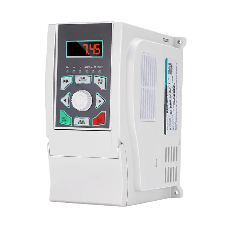
With the continuous improvement of industrial automation, frequency converters have become indispensable core components in motor drive systems. By adjusting output voltage and frequency, they achieve precise control of motor speed and play a key role in fans, water pumps, compressors, conveyors and other equipment. According to industry statistics, rational application of frequency converters can save 20%–60% energy for motor systems, significantly reducing enterprise operating costs.
However, the performance of a frequency converter is closely related to its installation quality, parameter configuration and daily maintenance. Improper installation may lead to electromagnetic interference and overheating tripping; incorrect parameters may cause motor stall or overload protection; negligent maintenance may result in premature aging or even damage to equipment. Faced with the above challenges, a systematic and standardized installation, commissioning and troubleshooting system is particularly important.
Zhejiang NENA Electric Co., Ltd. has been deeply engaged in the frequency converter field for many years and accumulated rich engineering application experience. Combined with the practical experience of the company’s technical team, this paper systematically summarizes technical points of the full life cycle of frequency converters from three dimensions: installation specifications, common fault analysis and practical application problems, for reference by engineering technicians.
Preparation Before Installation
2.1 Model Selection and Specification Verification
Before installation, confirm that the rated parameters of the frequency converter match the driven motor and load characteristics. Key verification points:
- Rated output power (kW) ≥ motor rated power
- Rated voltage consistent with input power (three-phase 380V or single-phase 220V)
- Rated current: 1.1–1.2 times the motor full-load current
- Overload capacity (150% × 60s or 120% × 60s) meets load requirements
- Control mode (V/F, vector control, DTC) matches process requirements
2.2 Installation Environment Requirements
Variable frequency drives impose strict requirements on their installation environment; an unfavorable environment is one of the primary causes of equipment failure. The requirements for a standard installation environment are as follows:
|
Environmental Parameter
|
Standard Requirement
|
Remarks
|
|
Operating Temperature
|
-10°C ~ +40°C
|
Derate above 40°C
|
|
Relative Humidity
|
≤ 90% (non-condensing)
|
Prevent condensation corrosion
|
|
Altitude
|
≤ 1000m
|
Derate if exceeded
|
|
Vibration & Shock
|
≤ 5.9m/s² (0.6g)
|
Avoid high-vibration machines
|
|
Protection Grade
|
IP20 or above
|
IP54+ for dusty/humid environment
|
|
Heat Dissipation Space
|
≥150mm top/bottom, ≥300mm front
|
Ensure ventilation
|
2.3 Tools and Consumables
- Insulated screwdrivers (slotted / Phillips)
- Digital multimeter
- Ground resistance tester
- Torque wrench
- Shielded cables
- Heat-shrink tubes, cold-pressed terminals, wire markers
- Electrical drawings and operation manual
Standard Installation Process
3.1 Mechanical Installation
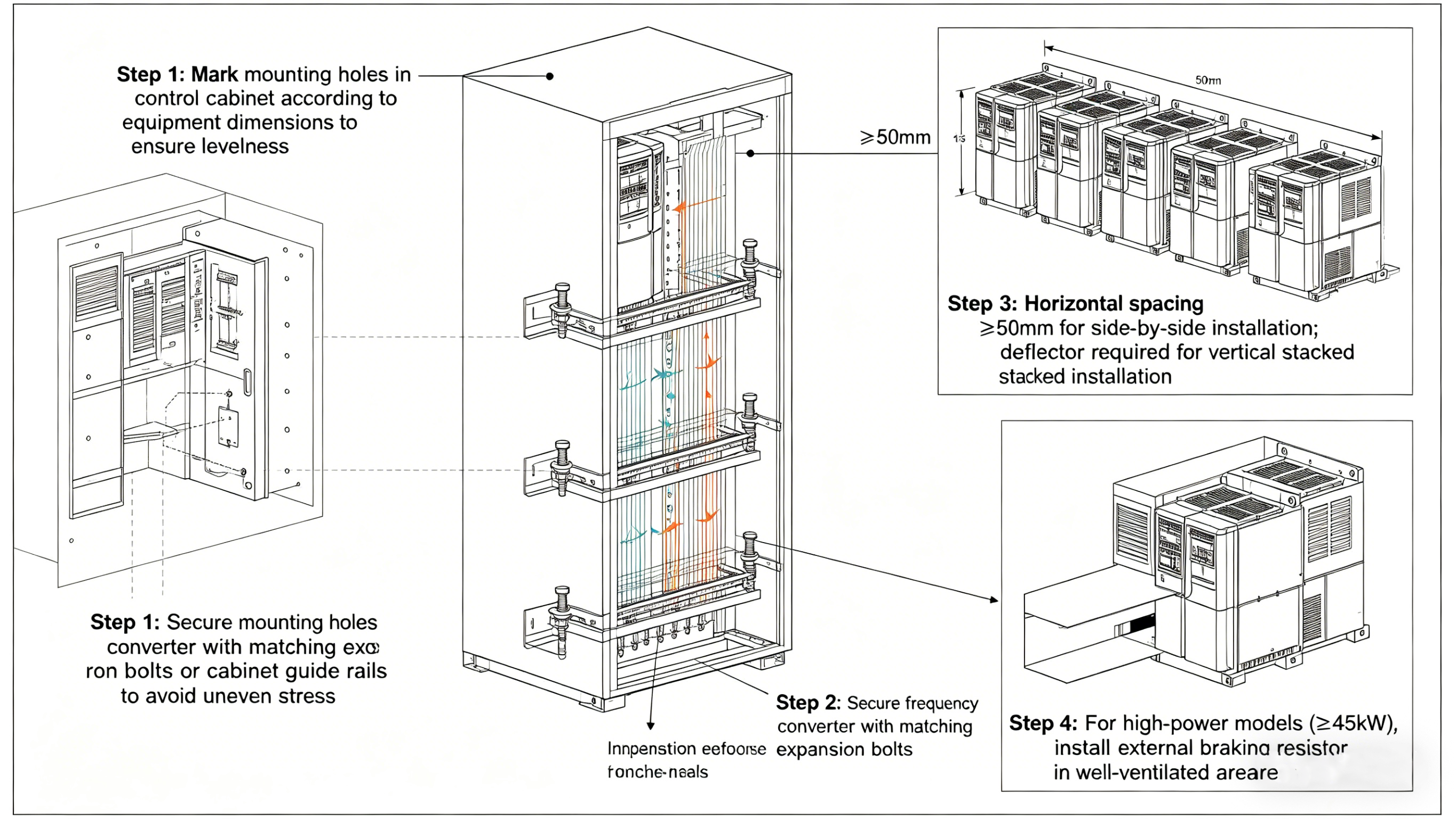
- Mark mounting holes in the control cabinet and keep level.
- Fix with expansion bolts or cabinet rails.
- Side-by-side installation: horizontal spacing ≥50mm; vertical stacking with baffles.
- High-power models (≥45kW): external braking resistor in well-ventilated area.
3.2 Electrical Wiring
3.2.1 Main Circuit Wiring
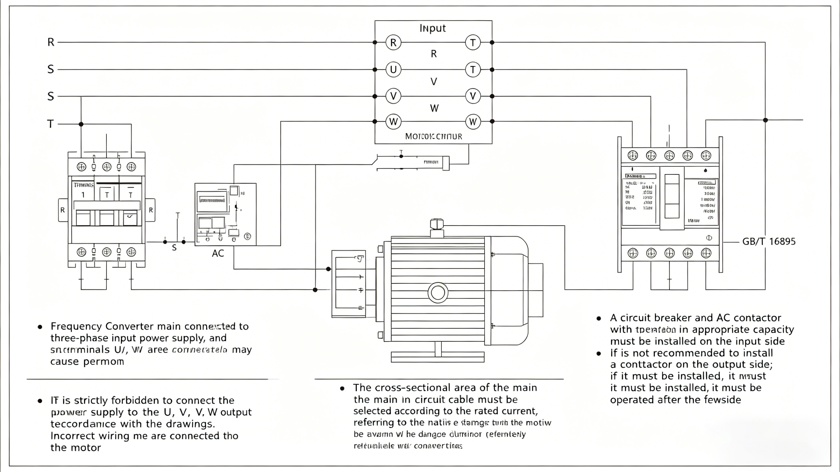
- R/S/T: input power; U/V/W: motor output.
- Do NOT connect power to U/V/W(will damage inverter).
- Cable cross-section selected per rated current (GB/T 16895).
- Input side: circuit breaker and contactor.
- Output side: contactor not recommended; if used, switch only after inverter stops.
3.2.2 Control Circuit Wiring
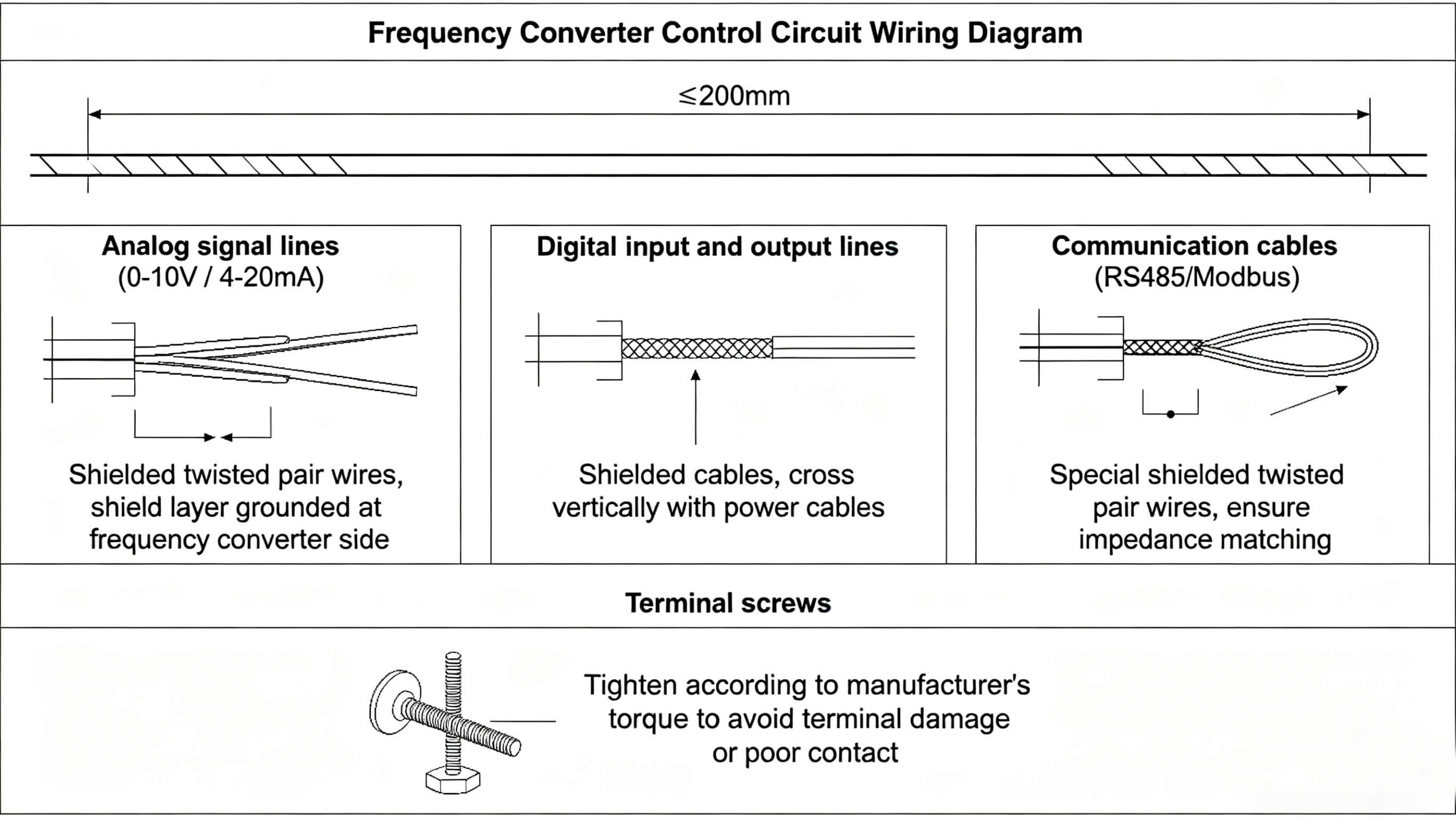
- Control cables and power cables routed separately, spacing ≥200mm.
- Analog signals (0–10V / 4–20mA): shielded twisted pair, single-end grounded (inverter side).
- Communication cables (RS485/Modbus): special shielded twisted pair with impedance matching.
- Tighten terminals to specified torque.
3.2.3 Grounding Specifications
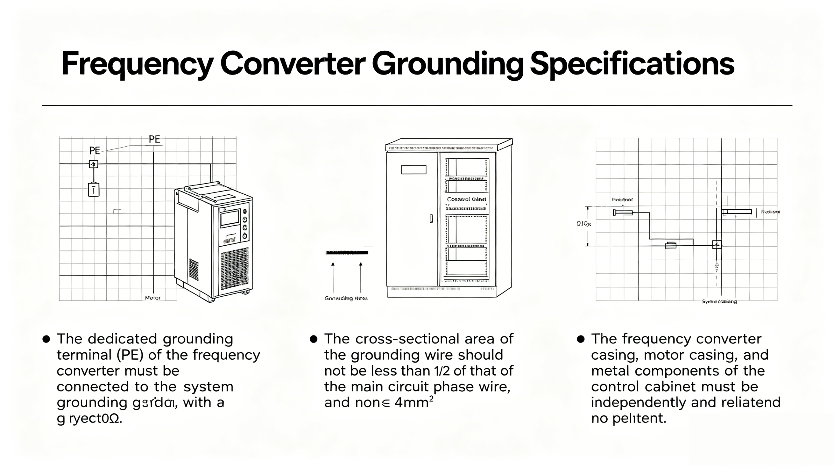
- PE terminal connected to system grounding grid, resistance ≤10Ω.
- Ground wire ≥1/2 of main phase wire, ≥4mm².
- Inverter case, motor case, cabinet metal parts: independent reliable grounding.
- Do NOT share ground with welding or high-power equipment.
Power-on Commissioning
4.1 Pre-power-on Check List
Before powering on for the first time, the following items must be verified one by one to prevent damage upon power-up:
|
Inspection Item
|
Content
|
Status
|
|
Wiring Verification
|
R/S/T input, U/V/W output correct
|
□ Confirmed
|
|
Insulation Test
|
Main circuit to ground ≥5MΩ (500V megohmmeter)
|
□ Confirmed
|
|
Grounding Check
|
PE grounded reliably, resistance ≤10Ω
|
□ Confirmed
|
|
Voltage Confirmation
|
Input voltage matches nameplate
|
□ Confirmed
|
|
Motor Parameters
|
Rated power/voltage/current/frequency recorded
|
□ Confirmed
|
|
Heat Dissipation Check
|
Fan installed, vents unobstructed
|
□ Confirmed
|
|
Fastening Check
|
All terminals tightened to torque
|
□ Confirmed
|
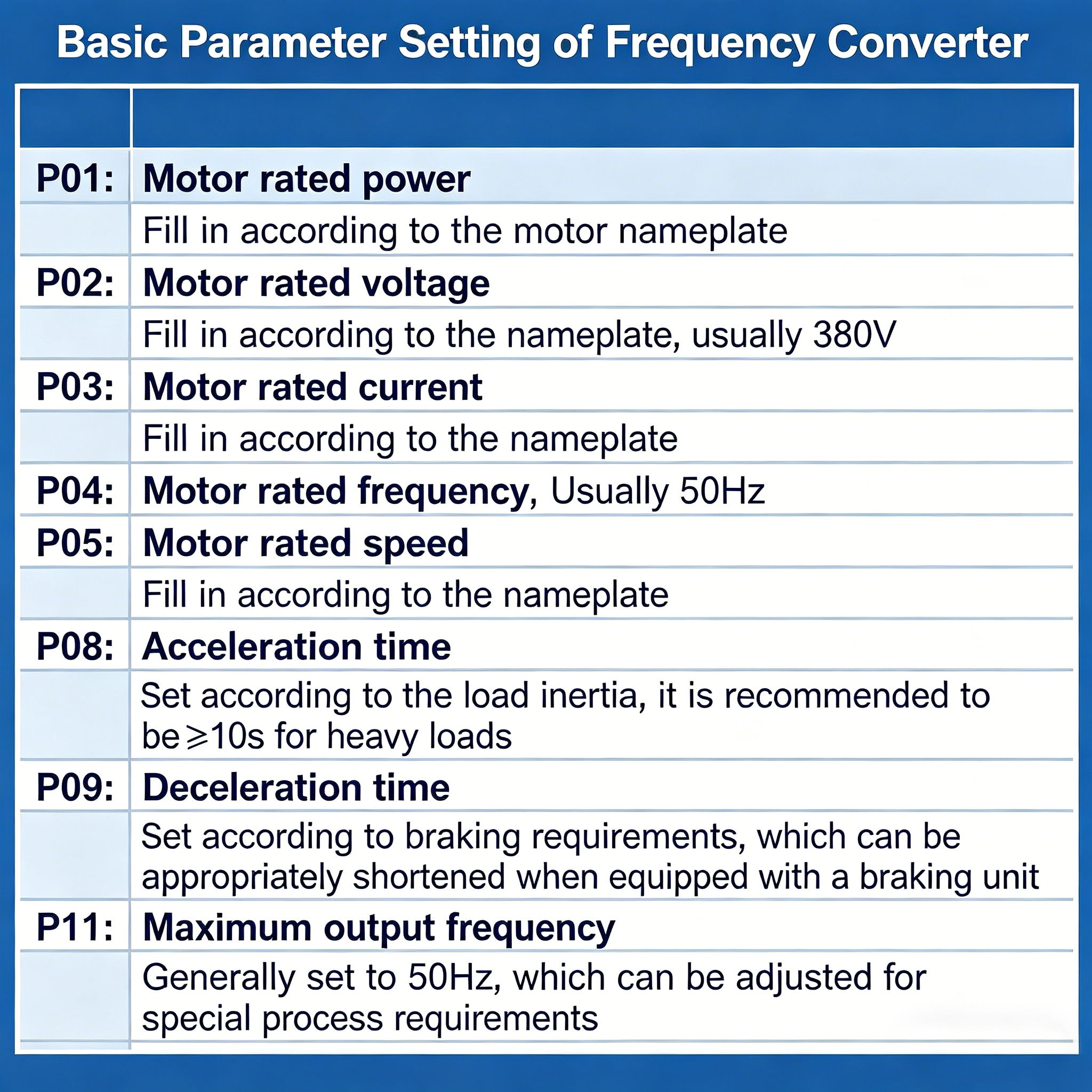
4.2 Basic Parameter Settings
- Motor rated power (P01)
- Motor rated voltage (P02)
- Motor rated current (P03)
- Motor rated frequency (P04, typically 50Hz)
- Motor rated speed (P05)
- Acceleration time (P08): ≥10s for heavy load
- Deceleration time (P09)
- Maximum output frequency (P11): normally 50Hz
4.3 Motor Auto-tuning
For vector control, perform auto-tuning to obtain stator resistance, rotor time constant, etc.
- Motor connected or disconnected from load
- Motor nameplate parameters correctly set
- Ensure safety during short operation
Common Fault Analysis and Troubleshooting
5.1 Overheat Protection (OHT / OH)
Fault: Overheat code, automatic stop, high casing temperature.Causes: High ambient temperature; fan failure/blockage; insufficient space; overload; dust on heat sink.Solutions: Improve ventilation; replace fan; clean heat sink; check load; adjust installation spacing.
5.2 Overload / Overcurrent (OL / OC)
Fault: Frequent tripping, especially on startup.Causes: Mechanical jam; too short acceleration time; wrong motor current; transmission failure; undersized inverter.Solutions: Remove jam; extend acceleration time; correct parameters; replace parts; upgrade inverter capacity.
5.3 Unstable Output Voltage (UV / LV)
Fault: Speed fluctuation, jitter, noise, undervoltage fault.Causes: Large voltage fluctuation; aging DC bus capacitor; poor contact; grid harmonics.Solutions: Install regulator/UPS; check capacitor; tighten terminals; add AC reactor/EMC filter.
5.4 Harmonic Interference
Fault: Instruments/PLC abnormal; unstable operation; grid interference.Solutions: Input AC reactor; output dV/dt filter; shielded cables; metal shielding; AFE inverter for high-harmonic sites.
5.5 Communication & Control Faults
Fault: PLC communication lost, Modbus/Profibus error.Causes: Parameter mismatch; wrong wiring; missing 120Ω resistor; poor grounding; firmware incompatibility.Solutions: Verify parameters; check wiring; add terminal resistors; improve grounding; update firmware.
5.6 Motor Not Running / Abnormal Speed
Fault Symptoms
The VFD displays no fault codes, yet the motor fails to start; alternatively, the operating frequency deviates significantly from the set value.
Common Causes and Countermeasures
|
Fault Phenomenon
|
Possible Cause
|
Solution
|
|
Frequency set but motor not running
|
Wrong start command source
|
Check panel/terminal/communication
|
|
Motor reverse rotation
|
U/V/W phase swapped
|
Swap wires or change direction parameter
|
|
Low speed
|
Low analog signal
|
Check input signal
|
|
Sudden stop
|
Overload/overheat/undervoltage
|
Check fault code
|
|
Trip during acceleration
|
Acceleration time too short
|
Extend acceleration time
|
|
Low torque at low speed
|
Improper V/F curve
|
Increase torque compensation or use vector control
|
Typical Application Problems and Solutions
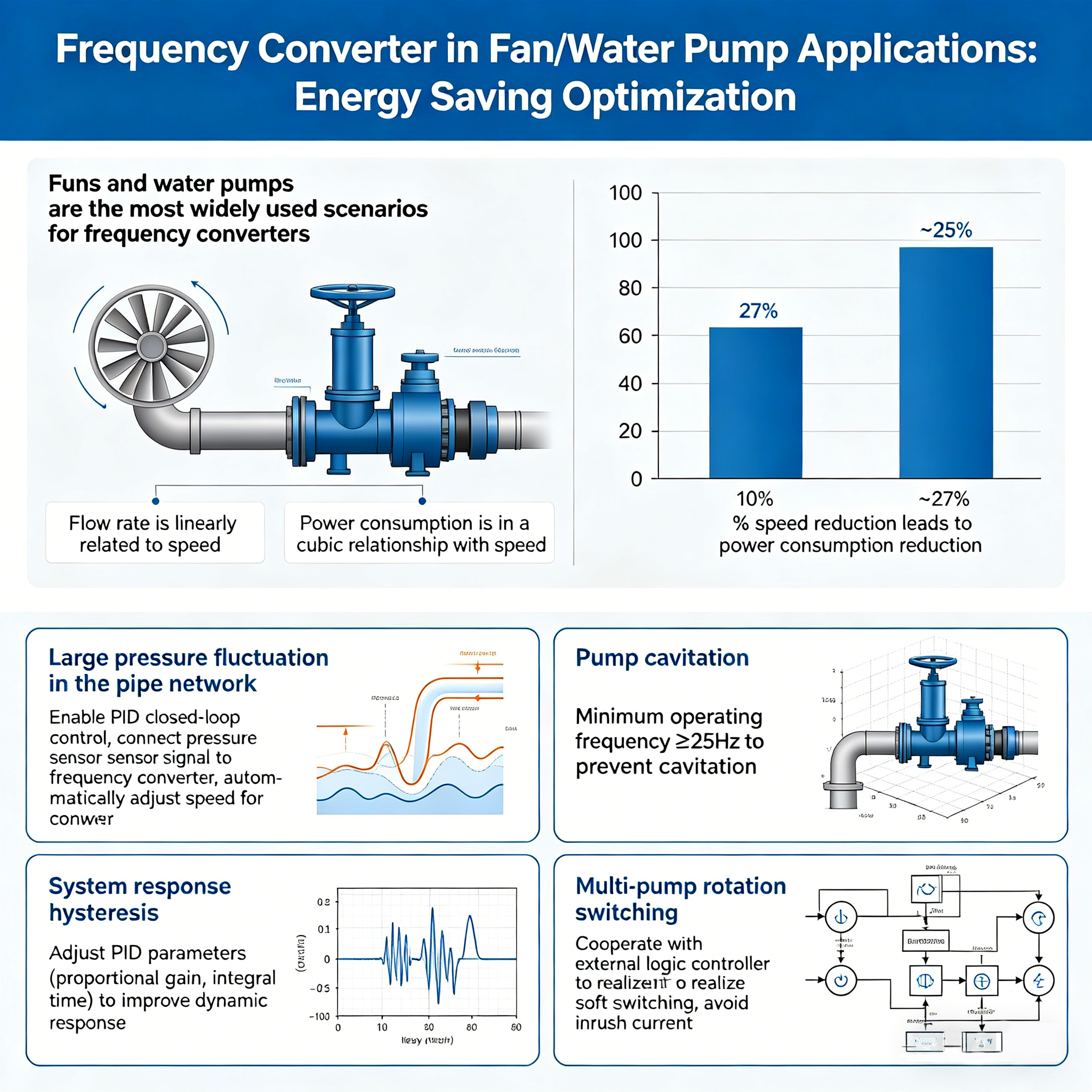
6.1 Fan / Pump: Energy Saving Optimization
- Pressure fluctuation: use PID closed-loop control
- Cavitation: minimum frequency ≥25Hz
- Slow response: adjust PID parameters
- Multi-pump switching: soft switching with external controller
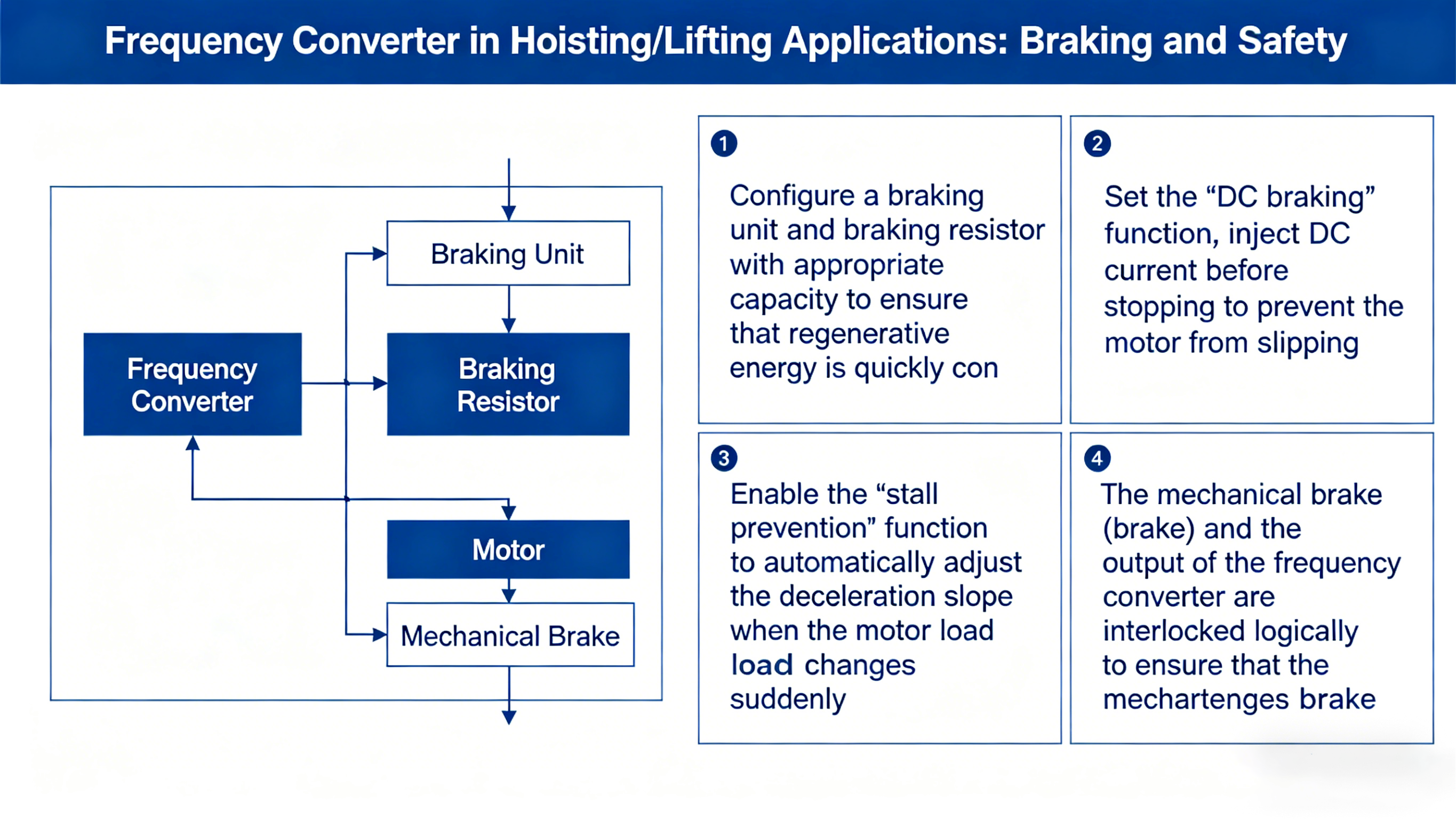
6.2 Lifting / Hoisting: Braking and Safety
- Matching braking unit and resistor
- DC braking function to prevent slipping
- Stall prevention function
- Mechanical brake interlock with inverter output
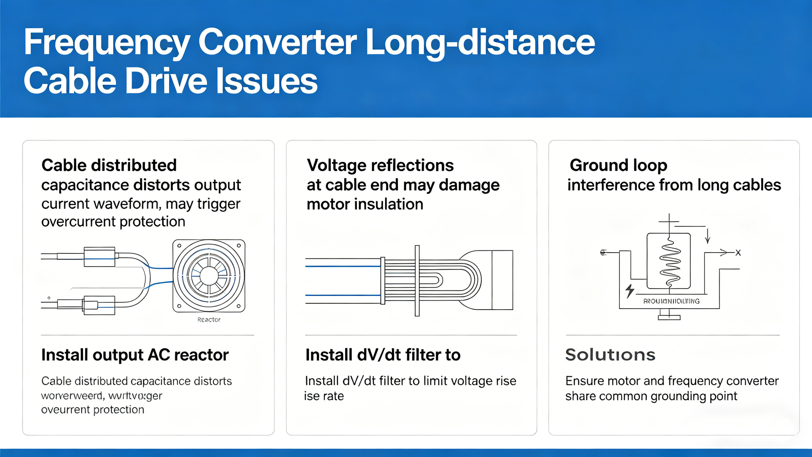
6.3 Long-distance Cable Drive (>50m)
- Install output AC reactor
- Install dV/dt filter
- Common grounding for inverter and motor
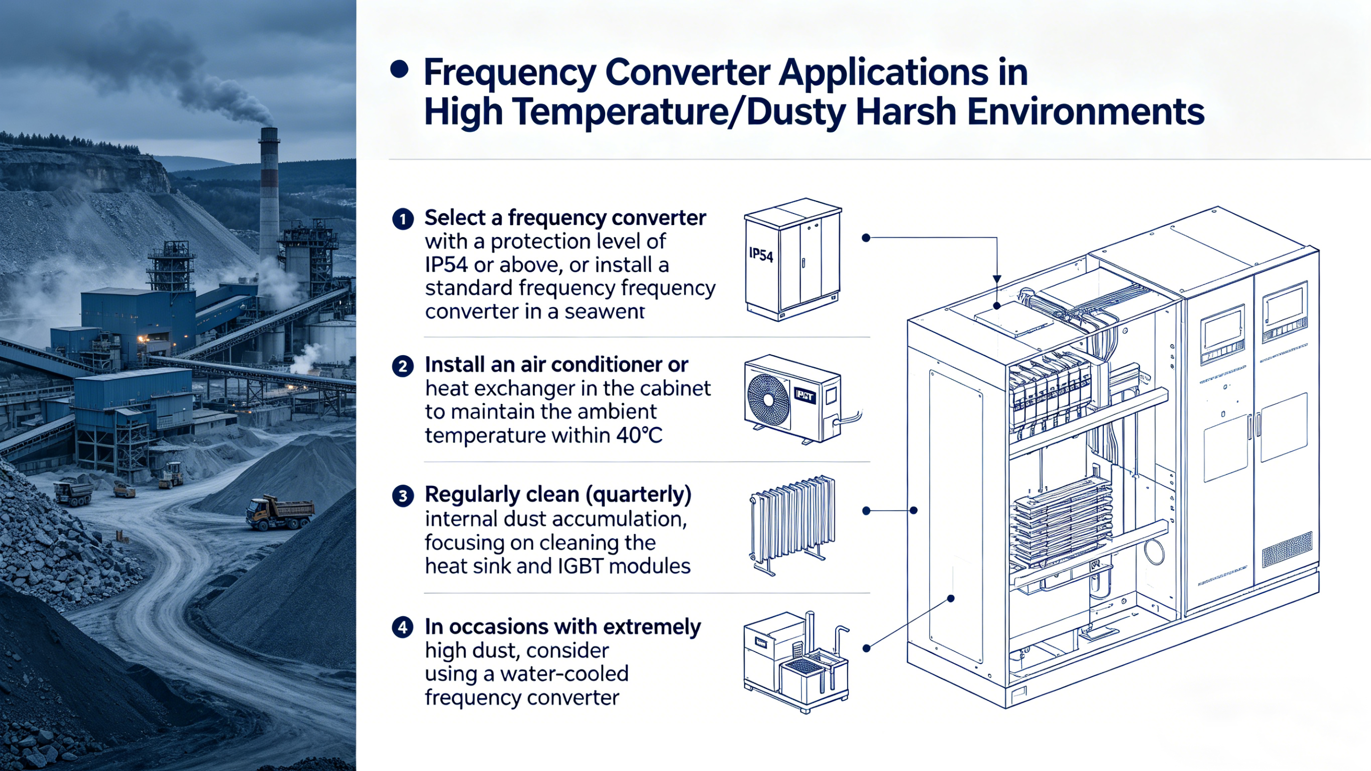
6.4 High Temperature / Dust Environment
- IP54+ or sealed cabinet with positive pressure ventilation
- Cabinet air conditioner / heat exchanger
- Quarterly cleaning of heat sink and IGBT
- Water-cooled inverter for heavy dust
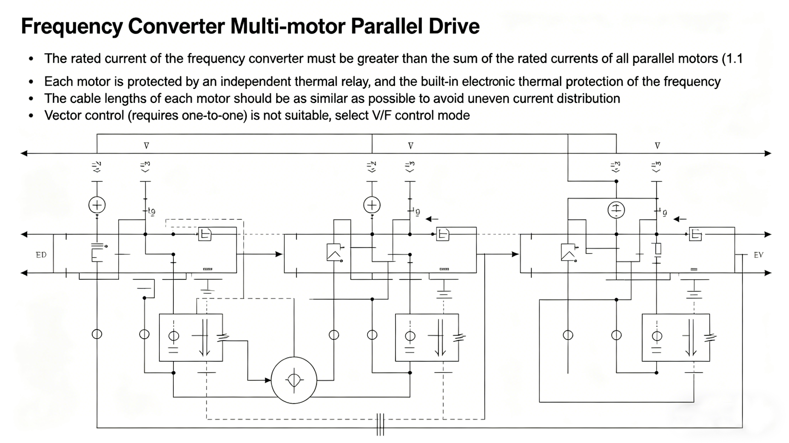
6.5 Multi-motor Parallel Drive
- Inverter current ≥ sum of motor currents ×1.1
- Independent thermal relay for each motor
- Similar cable length for each motor
- Use V/F control (not vector control)
Preventive Maintenance
Preventive maintenance is the most economical means of extending the service life of frequency converters and reducing the rate of unplanned downtime. It is recommended to establish the following maintenance plan:
|
Cycle
|
Item
|
Details
|
|
Daily
|
Monitor operation
|
Record current, temperature, frequency
|
|
Monthly
|
Appearance & environment
|
Clean vents, check temperature/humidity
|
|
Quarterly
|
Deep cleaning
|
Clean heat sink, check fan
|
|
Semi-annually
|
Electrical inspection
|
Tighten terminals, test insulation
|
|
Annually
|
Overhaul
|
Check capacitors, replace fan (every 3 years)
|
|
On demand
|
Firmware upgrade
|
Update for fixes and improvements
|
Electrolytic capacitors: service life 5–10 years; preventive replacement recommended.
Conclusion
Efficient and stable operation of a frequency converter depends on standardized management throughout selection, installation, commissioning and maintenance. This paper systematically summarizes installation specifications, commissioning procedures, and troubleshooting for six common faults: overheating, overload, voltage instability, harmonic interference, communication failure and motor abnormality. Targeted engineering solutions are proposed for fans/pumps, lifting, long-distance drive, harsh environments and multi-motor parallel applications.
Zhejiang NENA Electric Co., Ltd. provides professional technical support and after-sales service. Our engineers have rich on-site commissioning experience and can provide customized solutions for various industrial applications.
With the integration of IIoT and intelligent manufacturing, frequency converters will develop toward higher intelligence and networking: real-time monitoring, predictive maintenance and cloud remote diagnosis will become standard. Mastering current installation and troubleshooting skills is an important foundation for the intelligent drive era.
References
[1]Motor Factory Net. Troubleshooting Common Frequency Converter Issues. Zhejiang Ligong Motor Co., Ltd. Industry News, 2025.
[2] Anyhertz Drive. Troubleshooting Common Issues in Frequency Converter Operation. Anyhertz Drive (Shenzhen) Co., Ltd., 2024.
[3] Canroon Electric. Practical Tips for Solving Frequency Converter Commissioning Problems. Canroon Industry Insights, 2025.
[4] GoHz. Common Troubleshooting for Frequency Converter. GoHz Technical Resources, 2024.
[5] ATO. Frequency Converter Tech Support. ATO Technical Documentation, 2024.
[6] GB/T 12668.5-2013. Speed Electrical Drive Systems Part 5: Safety Requirements.
[7] IEC 61800-5-1:2022. Adjustable Speed Electrical Power Drive Systems – Part 5-1: Safety Requirements.
 English
 中文简体
中文简体 عربى
عربى


 浙公网安备33038202003754号