Zhejiang NENA Electric Co., Ltd.
Abstract
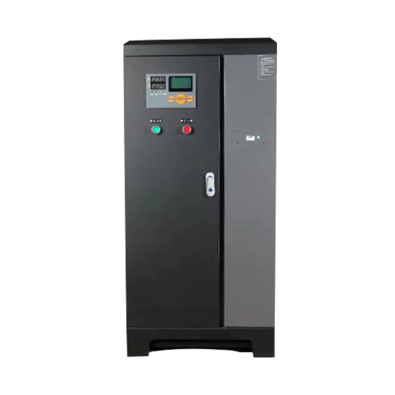
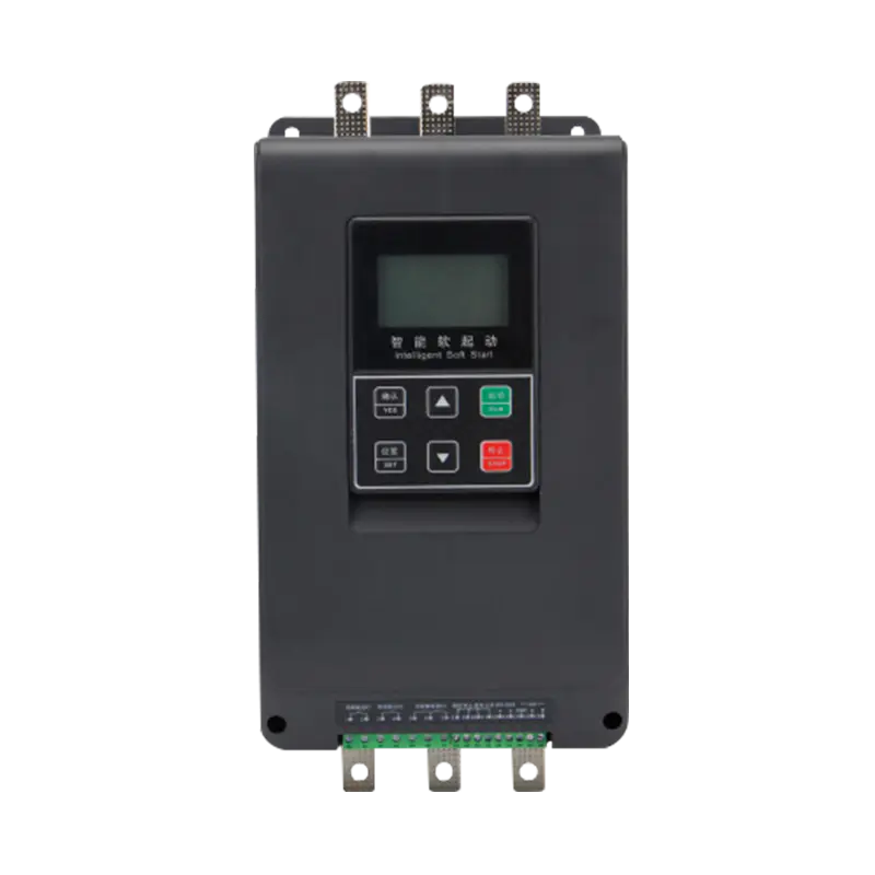
In modern industrial automation, the start‑up control of induction motors directly impacts equipment service life, grid stability, and production efficiency. A built‑in bypass soft starter, as an electrical control device integrating soft start and bypass functions, has become the mainstream selection solution for pumps, fans, compressors, conveyors, and other applications due to its compact structure, energy efficiency, and easy installation. This article systematically elaborates on the selection method of built‑in bypass soft starters from multiple dimensions, including working principles, core parameters, application scenarios, and selection steps, aiming to provide practical technical guidance for engineers.
Keywords: Induction Motor; Soft Starter; Built‑in Bypass; Selection Method; Motor Control
Introduction
Three‑phase AC induction motors are the most widely used drive equipment in industrial production. Their direct‑on‑line (DOL) starting current can reach 6–8 times the rated current, causing severe shocks to the grid and mechanical components such as transmission mechanisms, couplings, and belts. While traditional reduced‑voltage starting methods (e.g., star‑delta, autotransformer) mitigate these issues to some extent, they suffer from inherent drawbacks: significant switching shocks, complex control, and non‑adjustable parameters.
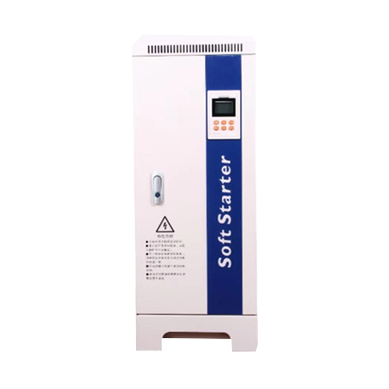
Soft starters solve these problems fundamentally by using silicon‑controlled rectifiers (SCRs) to smoothly ramp the motor voltage. A built‑in bypass soft starter automatically closes the bypass contactor after the soft start is complete, connecting the motor directly to the grid. This eliminates thermal losses from continuous SCR conduction and extends the service life of main power components.
However, with a wide variety of soft starters on the market, selecting the right model based on actual working conditions is critical for electrical engineers.
Working Principle of Built‑in Bypass Soft Starters
2.1 Soft Start Phase
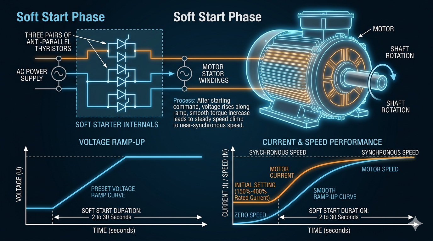
Upon a start command, the three pairs of anti‑parallel SCRs inside the soft starter gradually increase the voltage applied to the motor stator winding following a preset voltage ramp profile. The motor current rises smoothly from an initial set value (typically 150%–400% of the rated current), torque increases slowly, and speed ramps up to near synchronous speed. The entire process can be completed within 2–30 seconds (depending on load characteristics and settings).
2.2 Bypass Switching Phase
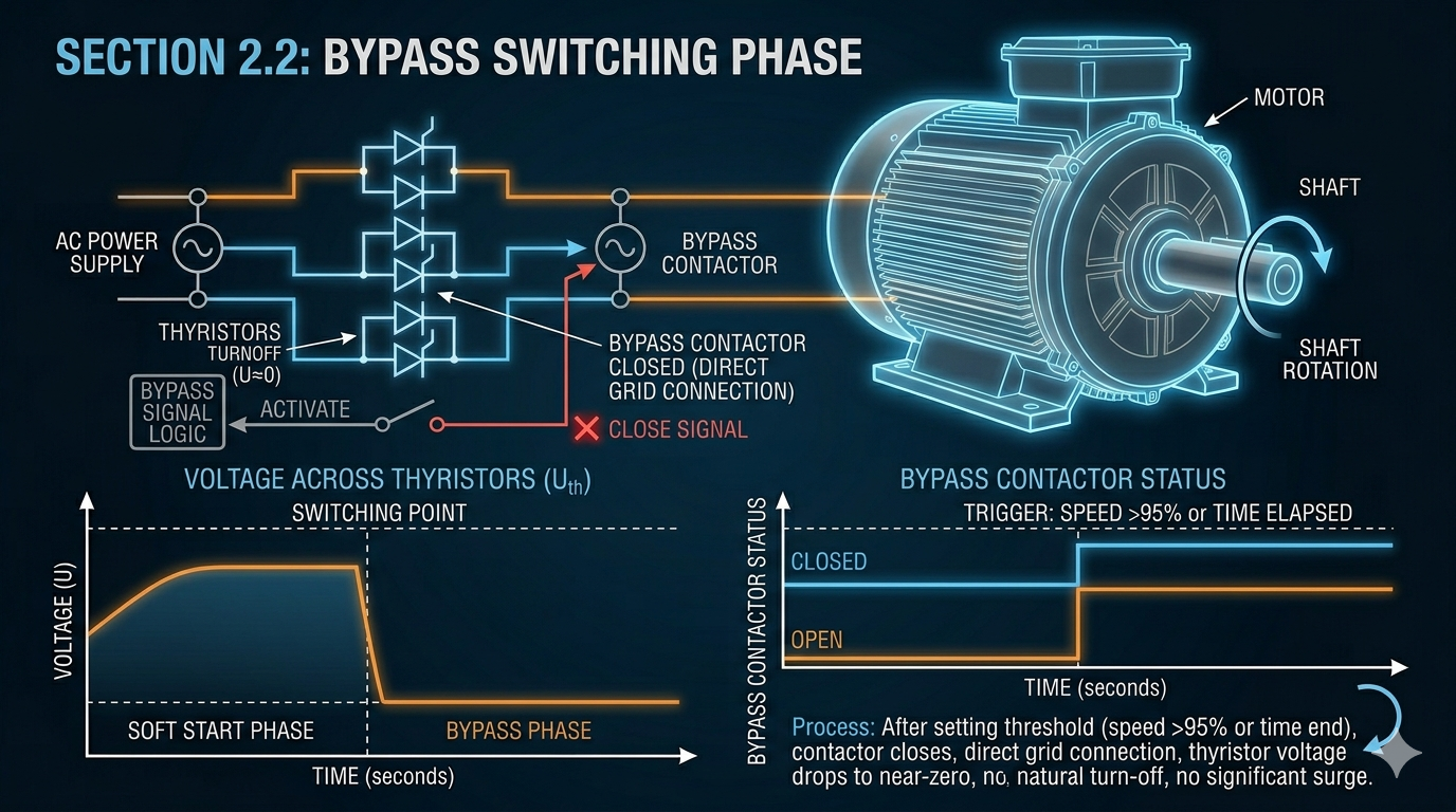
When the motor speed reaches a preset threshold (typically >95% of rated speed) or the start timer expires, the soft starter sends a close signal to the built‑in bypass contactor. The contactor closes, connecting the motor three‑phase windings directly to the grid. The voltage drop across the SCRs approaches zero, turning them off and removing them from the circuit. The switching process occurs without significant shock.
2.3 Normal Operation Phase
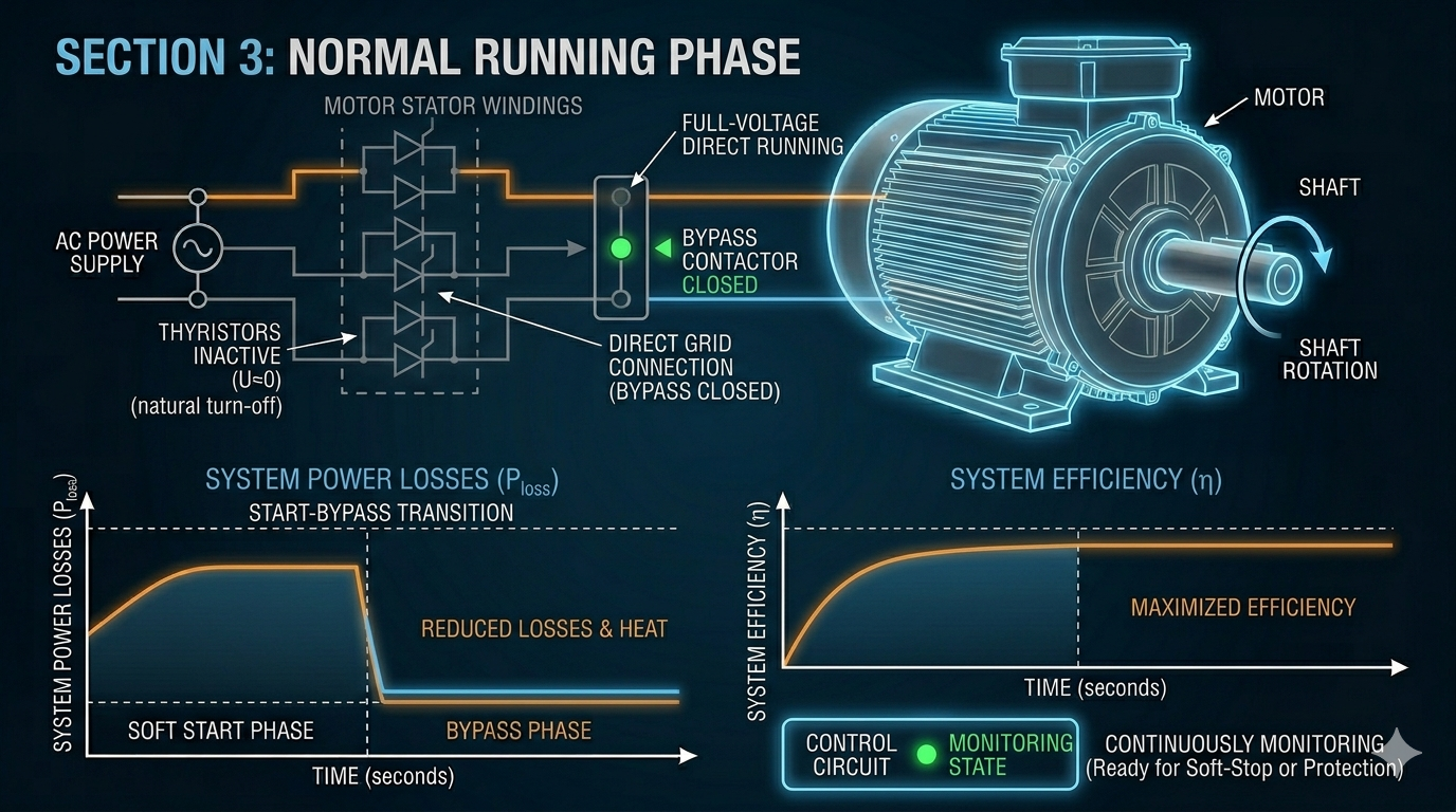
With the bypass contactor closed, the motor runs at full voltage. The main circuit no longer passes through the SCRs, eliminating additional losses and heat caused by the SCR conduction voltage drop (approximately 1.5–2V per device), ensuring optimal system efficiency. The soft starter’s control loop remains in a monitoring state, ready to execute soft stop or fault protection actions.
2.4 Soft Stop Phase (Optional)
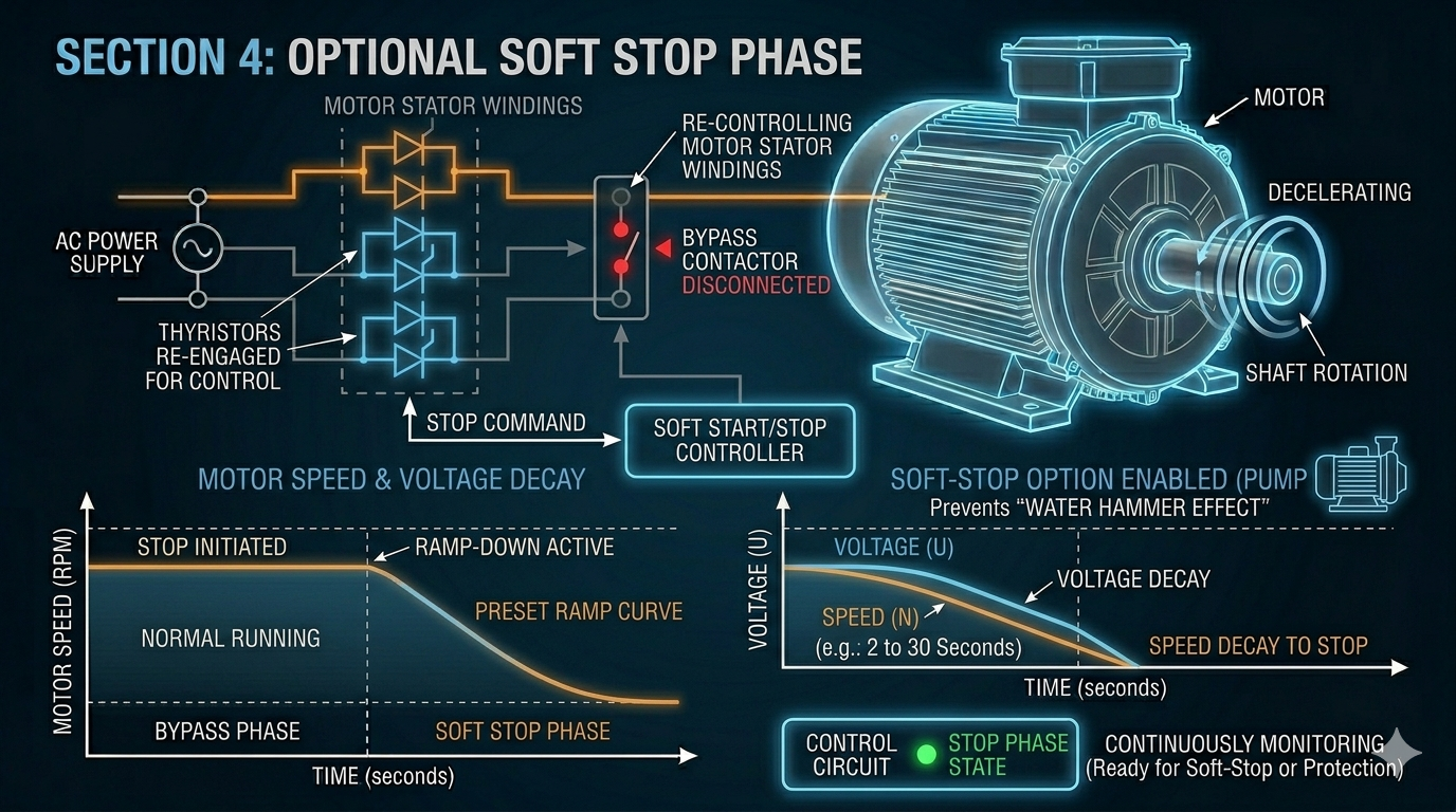
For applications such as pumps requiring protection against water hammer effects, the soft stop function can be enabled. Upon a stop command, the bypass contactor opens, and the SCRs resume control, smoothly reducing the motor voltage following a preset ramp profile until the motor stops.
Comparison: Built‑in vs. External Bypass Soft Starters
Before selection, engineers must clarify the essential differences between built‑in bypass and external bypass solutions to confirm the suitability for the project.
| Comparison Dimension |
Built‑in Bypass Soft Starter |
External Bypass Soft Starter |
| Structure |
Bypass contactor integrated into the main unit |
Contactor installed separately with external wiring |
| Space |
Compact, saves cabinet space |
Requires additional space for the contactor |
| Installation |
Simple, fewer connections, plug‑and‑play |
Extra wiring and terminal connections needed |
| Power Range |
Medium and low power (typically ≤630kW) |
High power, heavy‑duty, or custom applications |
| Maintenance |
Integrated unit, replaced as a whole |
Contactor can be replaced individually, reducing costs |
| Redundancy |
Lower |
Independent redundancy via external contactors |
| Cost |
Lower (high integration) |
Higher (additional contactor and accessories) |
| Best For |
General industrial applications, space‑limited cabinets |
High‑voltage, large‑capacity, high‑reliability critical applications |
Conclusion: For applications with a rated power of 630kW or less, no special redundancy requirements, and limited installation space, a built‑in bypass soft starter is the optimal choice.
Interpretation and Matching of Induction Motor Nameplate Data
Soft starter selection must be based on the motor nameplate. Below is a guide to key parameter interpretation.
4.1 Rated Power (kW) and Rated Current (A)
The soft starter’s rated current must be no less than the motor’s rated current. Note that the soft starter’s rated current refers to the continuous current capacity of the bypass contactor, not the SCRs. General recommendations:
- Standard duty (light load, frequent starts): Soft starter rated current ≥ Motor rated current × 1.0
- Heavy duty (high inertia, hard start): Soft starter rated current ≥ Motor rated current × 1.25~1.5
- Frequent starts (≥5 times/hour): Derate per the manufacturer’s derating curve.
4.2 Rated Voltage (V)
Must strictly match the grid voltage. Common low‑voltage ratings: 220V/380V/660V/1140V (AC). The soft starter’s operating voltage range must cover ±10% of the actual grid voltage fluctuation.
4.3 Motor Poles and Load Type
Different load characteristics demand significantly different starting torques.
- Centrifugal pumps, fans: Torque increases with the square of speed, low starting resistance, low starting current (2–3× rated current). Voltage ramp mode is suitable.
- Positive displacement pumps (screw, plunger): Constant torque, high starting resistance, requires high initial torque. Torque control or kick start functions recommended.
- Compressors: Medium starting resistance, requires smooth acceleration. Current limit mode recommended.
- Conveyors, mixers: High inertia, long start time. Verify the soft starter’s thermal capacity.
4.4 Start Class
IEC 60947‑4‑2 defines start classes (e.g., CLASS 10, CLASS 20, CLASS 30), corresponding to different thermal accumulation capabilities and allowable start times. Select based on actual start duration.
Core Selection Parameters for Built‑in Bypass Soft Starters
5.1 Starting Current Multiplier (Ie)
The allowable starting current range is typically 1.5–5× rated current (Ie). Select a reasonable limit to ensure sufficient torque while complying with grid voltage drop limits (typically ≤15%).
| Load Type |
Recommended Starting Current Limit (×Ie) |
| Centrifugal pumps, fans |
2.0~3.0 |
| Air compressors |
3.0~3.5 |
| Conveyors (full load start) |
3.5~4.5 |
| Mixers |
4.0~5.0 |
5.2 Ramp‑up Time
Balance two factors: too short = high inrush current; too long = excessive SCR heat. Typical range: 5–20 seconds; up to 30 seconds for heavy duty (verify thermal capacity).
5.3 Bypass Contactor Rating
The rated current of the built‑in bypass contactor must match the motor current. Its lifespan (electrical, mechanical) must meet operational demands. High‑quality models use AC‑3 class industrial contactors with an electrical life of >1,000,000 operations.
5.4 Protection Functions
A high‑quality soft starter should include:
- Overload Protection: Based on a thermal accumulation model, prevents the motor from operating under sustained overload conditions.
- Phase Loss / Phase Imbalance Protection: Detects imbalances in three-phase current or voltage, preventing the motor from operating in a single-phase mode.
- Undervoltage / Overvoltage Protection: Monitors for anomalies in the power supply voltage.
- Ground Fault Protection (Select Models): Detects insulation faults between the motor and ground.
- Locked Rotor Protection: Detects a stalled condition (failure of speed to rise) during the motor startup process.
- Startup Timeout Protection: Automatically trips the circuit if the startup process is not completed within the specified time limit.
5.5 Communication & Control Interfaces
Modern industrial automation systems impose increasingly stringent requirements on the communication capabilities of soft starters:
- Local Control: Panel buttons and digital displays
- Remote Control: External terminals (digital inputs/outputs)
- Fieldbus: Modbus RTU (RS-485), PROFIBUS-DP, DeviceNet, EtherNet/IP, etc., facilitating seamless integration with PLC/SCADA systems
- Parameter Backup: Certain high-end products support parameter cloning or SD card storage, simplifying batch commissioning and maintenance replacements
Installation Environment & IP Rating
Reliable operation depends on environmental conditions.
Ambient temperature: ‑10°C~+40°C. Derate 2%/°C above 40°C.
Altitude: Derate 1%/100m above 1000m. Above 2000m, use high‑altitude models or forced cooling.
IP rating (IEC 60529):
- IP20: Indoor cabinets (finger protection).
- IP55: Outdoor/dusty/humid environments (dust protected, splash proof).
- IP65/IP66: Washdown environments.
- Cooling: Allow ≥100mm clearance above/below. Ensure cabinet ventilation.
Application Cases
Case 1: Water Pump (Municipal Water Supply)
Motor: 132kW, 250A, 380V, centrifugal pump, 6–8 starts/day.
Requirements: Soft stop (water hammer), Modbus.
Selection:
≥250A model (e.g., 300A).
2.5×Ie start current, 8–12s ramp.
Soft stop 8–15s.
RS‑485/Modbus interface.
IP55 for outdoor cabinet.
Case 2: Fan (Industrial Ventilation)
Motor: 75kW, 142A, 380V, high‑inertia centrifugal fan, 2–3 starts/shift.
Requirements: Low noise, shockless start.
Selection:
15–20s ramp.
2.0–2.5×Ie start current, voltage ramp.
Kick start for static friction.
≥142A (e.g., 160A).
Case 3: Conveyor (Mining)
Motor: 250kW, 475A, 660V, heavy‑duty conveyor, full‑load start.
Requirements: Torque control, anti‑slip.
Selection:
660V model.
Torque boost mode.
4.0–4.5×Ie start current, 20–30s ramp.
550A or 630A rating (1.2–1.3× derate).
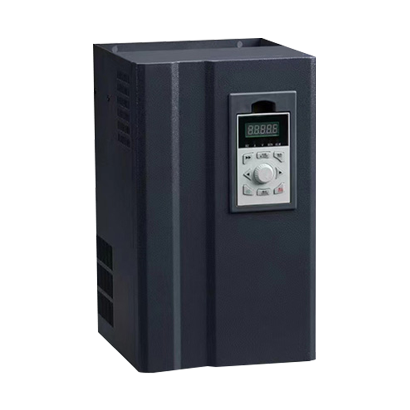
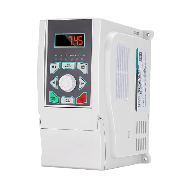
Soft Starter vs. Variable Frequency Drive (VFD)
| Comparison |
Built‑in Bypass Soft Starter |
VFD |
| Function |
Start/stop control |
Full‑speed regulation |
| Efficiency |
High (bypassed, no harmonic loss) |
Slightly lower (PWM harmonics) |
| Energy Saving |
Reduces start‑up losses |
Process savings via speed control |
| Cost |
Lower |
Higher (2–5× soft starter) |
| Harmonics |
Only during start |
Continuous (requires filtering) |
| Best For |
Fixed‑speed loads (pumps, fans) |
Variable‑speed processes |
Recommendation: Choose a built‑in bypass soft starter for fixed‑speed operation. Choose a VFD if continuous speed adjustment is required.
9. Certification & Compliance
Industrial soft starters should comply with:
IEC 60947‑4‑2
GB/T 21697 (China)
CE: LVD 2014/35/EU, EMC 2014/30/EU
UL/CSA (North America)
RoHS
10. Selection Checklist
Motor Data: Power, voltage, frequency, current, power factor, insulation, IP.
Load Profile: Type, torque, starts/hour, soft stop required, full‑load start.
Grid Conditions: Voltage, short‑circuit capacity, harmonics, max allowed voltage drop.
Environment: Temperature, altitude, humidity/dust, IP, mounting.
Control: Local/remote, communication (Modbus/PROFIBUS/EtherNet), I/O, PTC input.
Compliance: CE/UL/CCC, local codes.
Conclusion
Built‑in bypass soft starters offer high integration, energy efficiency, and easy maintenance. Correct selection ensures safe, reliable operation, extends equipment life, and reduces lifecycle costs.
A scientific selection process begins with motor and load analysis, followed by grid, environment, control, and certification considerations. Close collaboration with professional manufacturers is recommended for optimal technical and economic performance.
Zhejiang NENA Electric Co., Ltd. offers a 7.5kW~630kW product line with comprehensive protection and communication, certified by CE/GB, for water treatment, HVAC, chemical, mining, and metallurgy. Contact our engineers for support.
References
1. IEC 60947-4-2: 2011, Low-voltage switchgear and controlgear – Part 4-2: AC semiconductor motor controllers and starters.
2.GB/T 21697‑2023, Low‑voltage AC Semiconductor Motor Controllers and Starters
3.State Grid Corporation of China, Power Quality – Harmonics in Public Grids, GB/T 14549‑1993
4. Chapman, S.J. (2011). Electric Machinery Fundamentals (5th ed.). McGraw-Hill.
5. ABB Ltd. (2018). Technical Guide No. 1 – Direct torque control. ABB Drives.
6. Mohan, N., Undeland, T. M., & Robbins, W. P. (2003). Power Electronics: Converters, Applications, and Design (3rd ed.). John Wiley & Sons.



 English
 中文简体
中文简体 عربى
عربى




 浙公网安备33038202003754号