Abstract
The Frequency Converter—also known as a Variable Frequency Drive (VFD) or Variable Speed Drive (VSD)—is an indispensable core power electronic device in the field of modern industrial automation. Its fundamental function is to convert a fixed-frequency, fixed-voltage AC power supply into an AC output with adjustable frequency and voltage, thereby enabling the precise control of the rotational speed and torque of AC motors. Starting from the basic concepts of frequency converters, this paper systematically elucidates their core working principles (specifically, the AC-DC-AC conversion link), the circuit structures and technical parameters of their main functional modules, key control technologies (V/F control, vector control, and direct torque control), and their primary product types and industrial application scenarios. Furthermore, by incorporating an analysis of energy conservation and future technological development trends, this paper aims to provide a comprehensive and systematic technical reference for engineering professionals and industrial users.
Keywords: Frequency Converter; Working Principle; Pulse Width Modulation (PWM); Vector Control; Energy Conservation; Industrial Applications
I. Introduction
In modern industrial production and building electromechanical systems, electric motors constitute the most widely utilized power equipment, accounting for approximately 60% to 70% of total global industrial electricity consumption. Traditional fixed-frequency motors operate at a constant speed, making it difficult to flexibly adjust output power in response to actual operating conditions; this inflexibility results in significant energy waste. Taking centrifugal pumps and fans as examples: if traditional throttling methods are employed for regulation, a substantial amount of energy is dissipated uselessly as heat loss under low-load conditions. In contrast, frequency conversion control enables the motor speed to precisely match actual demand, yielding energy-saving efficiencies ranging from 20% to 50%.
The advent and widespread adoption of frequency converters have fundamentally transformed the methods by which AC motor speeds are controlled. Since the maturation of power semiconductor device technology (such as SCRs and IGBTs) in the 1970s, frequency converters have undergone a technological evolution ranging from analog to digital control, and from simple V/F control to high-performance vector control and direct torque control. Currently, frequency converters are widely deployed across virtually every industrial sector—including factory automation, HVAC systems, water management, new energy generation, and rail transportation—emerging as one of the core pieces of equipment for achieving industrial energy conservation, carbon reduction, and enhanced system automation levels. Zhejiang NENA Electric Co., Ltd. has dedicated itself to the fields of power electronics and industrial automation for many years, specializing in the R&D and manufacturing of variable frequency drives (VFDs), low-voltage electrical appliances, and industrial control systems. This document aims to provide a systematic exposition of the working principles and core technical details of VFDs, with the objective of offering in-depth technical reference to our customers, partners, and industry peers.
II.Basic Concepts and Classification of Variable Frequency Drives
2.1 Definition and Basic Functions
A variable frequency drive (VFD) is a power conversion device that utilizes power electronic components to transform utility-frequency AC power (typically 50 Hz or 60 Hz) into AC power with adjustable frequency and voltage. According to International Electrotechnical Commission (IEC) standards, the core function of a VFD is to alter the synchronous speed (n₁) of an asynchronous motor by varying the output frequency (f)—while maintaining the motor's magnetic flux essentially constant (thereby preserving its rated torque output capability)—thereby achieving continuous, stepless regulation of the motor's rotational speed.
Based on the speed formula for asynchronous motors—n₁ = 60f / p (where p represents the number of pole pairs in the motor and f represents the power supply frequency)—it is evident that by altering the supply frequency (f), the motor's synchronous speed can be changed linearly; this constitutes the fundamental physical basis for variable frequency speed control.
2.2 Primary Classifications
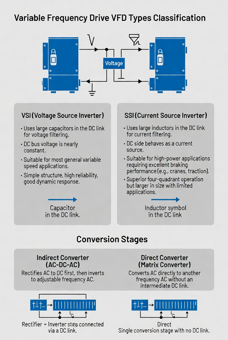
Based on the type of energy storage component utilized in the DC link, VFDs can be broadly categorized into the following two mainstream types:
- Voltage Source Inverter (VSI): The DC link employs large-capacitance capacitors for filtering, resulting in an approximately constant DC bus voltage. This type is suitable for the majority of general-purpose variable frequency speed control applications; it currently holds the largest market share among VFD types, offering advantages such as simple structure, high reliability, and excellent dynamic response.
- Current Source Inverter (CSI): The DC link employs large inductors for filtering, causing the DC side to exhibit current-source characteristics. This type is suitable for high-power applications with stringent braking performance requirements (e.g., hoisting and traction systems); it features excellent four-quadrant operation capabilities, though it tends to be larger in physical size and has a relatively more limited range of application scenarios. Furthermore, based on the number of conversion stages, variable frequency drives (VFDs) can be classified as follows:
- Indirect Converters (AC-DC-AC): These devices first rectify AC power into DC power, and then invert it back into AC power with an adjustable frequency. This represents the currently most mainstream technological approach.
- Direct Converters (AC-AC; Matrix Converters): These devices lack an intermediate DC link, directly converting AC power of one frequency into AC power of another frequency. While offering higher efficiency, their control mechanisms are complex; consequently, they remain in the market promotion and adoption phase.
III.Core Operating Principles of VFDs (AC-DC-AC)
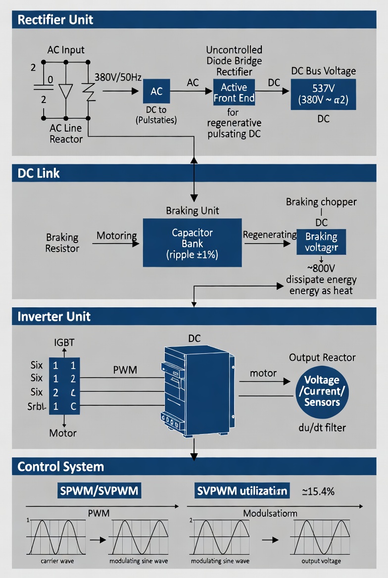
Mainstream VFDs employ a two-stage power conversion architecture known as AC-DC-AC. The entire power conversion process can be divided into three core stages—rectification, DC link filtering, and inversion—all of which are centrally coordinated and managed by a dedicated control system.
3.1 Rectifier Unit
The rectifier unit serves as the input stage of the VFD. Its function is to convert the utility-frequency AC power supplied by the power grid (typically single-phase 220V/50Hz or three-phase 380V/50Hz) into a pulsating DC voltage. Industrial-grade VFDs typically utilize a three-phase full-wave uncontrolled rectifier bridge (comprising six rectifier diodes). Following rectification—assuming a rated three-phase input of 380V—the DC bus voltage is approximately 537V (calculated as the RMS line voltage multiplied by √2; i.e., 380V × 1.414 ≈ 537V).
For high-performance applications requiring energy feedback (regenerative braking) capabilities, controlled rectifier bridges (utilizing Thyristors/SCRs) or Active Front End (AFE) technology are employed. These advanced solutions not only enable the feedback of motor braking energy back into the power grid but also effectively improve the input power factor and mitigate harmonic pollution within the grid, thereby ensuring compliance with harmonic standards such as IEC 61000-3-12.
3.2 DC Link (Intermediate Circuit)
The pulsating DC voltage produced by the rectifier unit must undergo smoothing and filtering within the DC link (intermediate circuit) to ensure the delivery of a stable DC bus voltage to the inverter unit. The DC link of a voltage-source inverter consists of large-capacity aluminum electrolytic capacitors, typically ranging in capacity from several hundred to several thousand microfarads (μF); these capacitors serve to suppress DC bus voltage ripple to within 1%. The stability of the DC bus voltage directly impacts the quality of the output voltage waveform generated by the inverter unit.
A branch containing a braking resistor and a braking unit (BU) is typically connected in parallel across the DC bus. When the motor decelerates, mechanical inertia causes it to enter a regenerative braking mode, feeding energy back into the DC bus and resulting in a rise in bus voltage. When the bus voltage exceeds a preset threshold (typically around 800 V), the braking unit activates, dissipating the excess energy as heat through the braking resistor to prevent damage to the inverter caused by overvoltage.
3.3 Inverter Unit
The inverter unit constitutes the core power conversion stage of the inverter; its function is to reconstruct the DC bus voltage into three-phase AC power with precisely controllable frequency and voltage amplitude. Modern inverters widely employ Insulated Gate Bipolar Transistors (IGBTs) as their switching devices. IGBTs offer numerous advantages—including high switching speeds (with switching frequencies ranging from 2 kHz to 16 kHz), low drive power requirements, low on-state voltage drop, and a wide safe operating area—making them the current mainstream choice for power semiconductor devices.
The three-phase inverter bridge is composed of six IGBTs (one for each of the upper and lower arms per phase). Driven by PWM signals generated by the control system, these IGBTs switch on and off according to a specific timing sequence to produce an equivalent sinusoidal PWM voltage waveform at the three-phase output terminals. Due to the significant inductive reactance of the motor windings, they naturally act as a low-pass filter for the high-frequency PWM carrier signal; consequently, the actual current waveform flowing through the motor windings closely approximates a pure sine wave, thereby enabling smooth motor operation.
3.4 Pulse Width Modulation (PWM) Technology
Pulse Width Modulation (PWM) is the core technology utilized for synthesizing the output voltage waveform of an inverter. Its fundamental principle is as follows: within a fixed carrier period, by adjusting the pulse width of the IGBT switching signals (i.e., the duty cycle), a series of rectangular pulses—equal in amplitude but varying in width—is generated such that their equivalent area matches the area of the desired sinusoidal waveform over the corresponding time interval. This process effectively generates a sinusoidal voltage of the required frequency and amplitude at the load terminals.
Currently, the most prevalent PWM modulation strategies are Sinusoidal Pulse Width Modulation (SPWM) and Space Vector Pulse Width Modulation (SVPWM). Compared to SPWM, SVPWM offers approximately 15.4% higher utilization of the DC bus voltage (reaching a factor of √3/3) and exhibits lower harmonic content; consequently, it is the preferred modulation scheme for modern high-performance variable frequency drives (VFDs). The selection of the PWM carrier frequency significantly impacts system performance: a higher carrier frequency results in a smoother output current waveform and reduced motor operating noise; however, it also leads to increased IGBT switching losses and a corresponding reduction in the VFD's overall efficiency. Therefore, the carrier frequency is typically optimized and selected within the 2 kHz to 16 kHz range based on the specific application scenario.
IV.Key Functional Modules and Circuit Structure
4.1 Main Circuit Structure
The main circuit of a variable frequency drive consists of three primary components connected in series—a rectifier bridge, a DC bus (comprising filtering capacitors and a braking unit), and an inverter bridge—thereby forming a complete power conversion path. On the input side, an AC line reactor is typically installed to suppress grid-side harmonic interference and improve the power factor. On the output side, an optional output AC reactor or *du/dt* filter may be added to mitigate the abrupt voltage transients (*du/dt*) caused by PWM switching, thereby protecting the motor's insulation, minimizing electrical erosion damage to the motor bearings, and enabling reliable operation over long cable runs spanning hundreds of meters.
4.2 Control System
The control system of a modern variable frequency drive is centered around a high-performance Digital Signal Processor (DSP) or Microcontroller (MCU). It integrates a wide array of functions, including analog and digital signal acquisition, protection logic, communication interfaces, and human-machine interaction capabilities. The control system continuously samples key parameters—such as DC bus voltage, three-phase output currents, and motor speed (derived from encoder feedback or sensorless estimation)—executes corresponding control algorithms (V/F control, vector control, or DTC), and generates precise PWM drive signals for output to the IGBT gate driver circuits.
The control system also incorporates comprehensive protection functions, including: overcurrent protection, overvoltage/undervoltage protection, overheat protection (based on NTC temperature sensors within the power module), ground fault protection, and motor overload protection (based on an i²t thermal protection model). These measures ensure the safe operation of both the variable frequency drive (VFD) and the driven motor under various abnormal operating conditions.
4.3 Drive Circuits and Power Modules
The IGBT gate driver circuit serves as the critical interface connecting the control system to the main power circuit. A high-quality gate driver circuit must provide sufficient gate drive current (typically ±2A to ±10A) to ensure rapid and reliable switching of the IGBTs. Simultaneously, it must provide high-voltage isolation between the control side and the power side (typically ≥2500 Vrms) to prevent high-voltage transients from damaging the control circuitry. Furthermore, the gate driver circuit integrates functions such as desaturation detection, short-circuit protection, and Miller clamping, providing rapid, hardware-level protection for the IGBT devices.
Power modules typically integrate the rectifier bridge, braking switch, and inverter bridge into a single package, adopting the form of a Power Integrated Module (PIM) or an Intelligent Power Module (IPM). IPMs feature internally integrated gate driver circuits and protection functions, thereby further enhancing system integration and reliability; they represent the mainstream choice for low-to-medium power variable frequency drives.
V. Detailed Explanation of Key Control Technologies
5.1 V/F Control (Voltage-to-Frequency Ratio Control)
V/F control (Voltage/Frequency Control) is the most fundamental and widely utilized control strategy for variable frequency drives. Its core principle involves adjusting the output voltage (V) in direct proportion to the output frequency (f). By maintaining a constant V/f ratio (i.e., the voltage-to-frequency ratio), the magnetic flux within the motor's air gap remains essentially constant. This ensures that, within the frequency range below the motor's rated frequency, the motor maintains a near-constant maximum torque output capability. V/F control features a simple structure, requires no specific motor parameters, and demonstrates strong adaptability to the controlled motor; it is well-suited for energy-saving variable-speed applications involving square-law torque loads, such as fans and pumps. Its limitations include limited dynamic performance—specifically, slow torque response at low speeds—and relatively low speed accuracy (typically around ±3%) due to its open-loop control nature; consequently, it is unsuitable for applications demanding high dynamic response capabilities and precise positioning accuracy.
5.2 Vector Control (Vector Control / FOC)
Field-Oriented Control (FOC)—also known as Vector Control—is currently the mainstream technology for high-performance variable-frequency speed regulation. Its core principle involves using coordinate transformations (specifically, the Clarke and Park transformations) to decouple the stator currents of a three-phase AC motor into two independent components: a flux component (Id*, controlling the magnetic field) and a torque component (*Iq*, controlling the torque). This approach enables independent control of the magnetic field and torque—analogous to that of a DC motor—thereby achieving superior dynamic response characteristics and a wide range of speed control capabilities.
Vector control is broadly categorized into two types: Closed-Loop Vector Control (CLVC)—also known as sensor-based vector control—and Open-Loop Vector Control (OLVC), or Sensorless Vector Control. Sensor-based vector control utilizes an incremental encoder (typically with a resolution of 1024 PPR or 2048 PPR) mounted on the motor shaft to precisely acquire speed and position information, thereby achieving high-performance control metrics such as a speed accuracy of ±0.02% and a torque response time of less than 5 ms. Conversely, sensorless vector control employs advanced mathematical motor models (such as full-order adaptive state observers or Kalman filters) to estimate the motor speed and rotor flux linkage; this eliminates the need for an encoder, thereby reducing system costs and simplifying maintenance. With a typical speed accuracy of approximately ±0.5%, sensorless vector control is suitable for the majority of industrial drive applications.
5.3 Direct Torque Control (DTC)
Direct Torque Control (DTC) was first proposed and commercialized by ABB in 1986. DTC requires neither a motor speed sensor nor complex coordinate transformations—unlike vector control—but instead directly calculates the actual values of motor flux linkage and torque within the stator coordinate system. By utilizing hysteresis comparators and a voltage vector selection table, it directly selects the optimal inverter switching state to maintain both the flux linkage magnitude and the torque within their respective hysteresis bands.
The core advantage of DTC lies in its extremely rapid torque dynamic response speed (typically < 2 ms) and its strong robustness against variations in motor parameters. It is particularly well-suited for high-performance drive applications—such as rolling, hoisting, and papermaking—where the requirements for dynamic torque quality are exceptionally high. Its primary drawbacks are relatively significant torque ripple at low speeds and a variable switching frequency, which may lead to additional noise and harmonic issues.
VI. Key Technical Parameters and Selection Criteria
In engineering practice, the proper selection of a variable frequency drive (VFD) is crucial for ensuring the reliable operation of the system and fully realizing its energy-saving benefits. Key Selection Parameters Include:
|
Parameter Name
|
Typical Range/Specification
|
Description
|
|
Rated Input Voltage
|
3-phase 380V±15% / 1-phase 220V±15%
|
Must match the grid voltage level
|
|
Rated Input Frequency
|
50Hz / 60Hz (±5%)
|
Adapts to grid frequencies in different countries
|
|
Output Frequency Range
|
0.00Hz – 400Hz (Configurable)
|
Determines the motor's maximum and minimum speeds
|
|
Rated Power Range
|
0.4kW – Several Thousand kW
|
Must be no lower than the rated power of the driven motor
|
|
Control Mode
|
V/F, SVC (Sensorless Vector Control), FOC
|
Selected based on process requirements for dynamic performance
|
|
Overload Capacity
|
150% / 60s, 180% / 3s (Heavy-duty type)
|
Must satisfy peak torque demands during load startup and sudden load changes
|
|
Protection Class (IP/NEMA)
|
IP20 – IP66 (NEMA 1 – 4X)
|
elect the appropriate protection class based on the installation environment
|
|
PWM Carrier Frequency
|
2kHz – 16kHz (Adjustable)
|
Higher carrier frequencies result in lower noise but impose stricter heat dissipation requirements
|
|
Communication Interface
|
Modbus RTU/TCP, CANopen, PROFIBUS, etc.
|
Enables integration with PLC, DCS, and SCADA systems
|
|
Cooling Method
|
Natural Convection, Forced Air Cooling, Water Cooling
|
High-power frequency converters typically employ forced air cooling or water cooling
|
Table 1: Overview of Key Technical Parameters for Frequency Converters
VII. Energy-Saving Principles and Energy Efficiency Analysis
The core basis for energy saving using frequency converters lies in the "Flow-Power Cube Law" (Affinity Law) applicable to fluid machinery: For centrifugal pumps and axial-flow fans operating under variable-speed control conditions, the flow rate Q is directly proportional to the rotational speed n; the head (pressure) *H* is directly proportional to the square of the speed; and the shaft power *P* is directly proportional to the cube of the speed. That is:
P₂ / P₁ = (n₂ / n₁)³ = (Q₂ / Q₁)³
Calculated by example: If a fan has a rated power of 100 kW under rated operating conditions, but process requirements call for only 80% of the rated flow rate, using traditional damper throttling control results in virtually no change in power consumption (remaining at approximately 80–90 kW). However, if variable frequency speed control is employed to reduce the rotational speed to 80%, the theoretical power consumption drops to just 100 × 0.8³ = 51.2 kW; this represents a power saving of approximately 38.8 kW, achieving a power-saving rate of 38.8%.
Furthermore, through its soft-start function—which limits the motor starting current to within 1.5 times the rated current (compared to the 6–8 times rated current surge experienced during direct-on-line starting)—the variable frequency drive (VFD) effectively mitigates the impact on the power grid during startup. It also significantly reduces the mechanical stress placed on the motor and transmission components, thereby extending equipment service life and lowering maintenance costs.
From a Total Life Cycle Cost (LCC) perspective, for high-power motors operating continuously, the initial capital expenditure (CAPEX) for a VFD can typically be fully recouped within 1 to 3 years through electricity cost savings (OPEX). Thereafter, the system continues to generate substantial economic benefits and carbon emission reductions, offering an exceptionally high return on investment.
VIII. Typical Industrial Application Scenarios
8.1 Factory Automation and Manufacturing
In fields such as CNC machine tool spindle drives, variable frequency control for hydraulic pumps in injection molding machines, textile machinery (warping machines, sizing machines, stenters), printing and packaging lines, and automated warehouse stacker cranes, VFDs enable high-precision control of speed, torque, and position. This significantly enhances product quality consistency and production efficiency, serving as a foundational support technology for Industry 4.0 smart manufacturing.

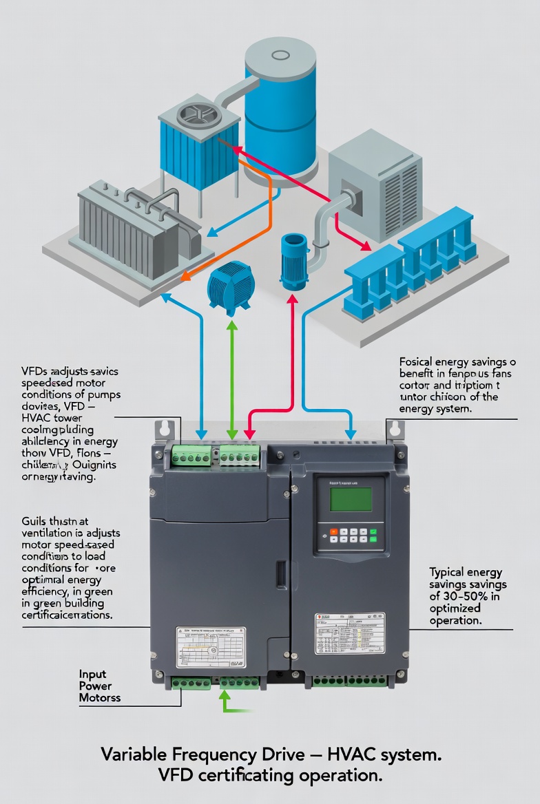
8.2 HVAC Systems
In central air conditioning systems, VFDs are widely utilized to drive chilled water circulation pumps, cooling water circulation pumps, cooling tower fans, and air handling unit supply fans. Based on variations in indoor load (indicated by feedback signals from temperature, differential pressure, or CO₂ concentration sensors), the variable frequency drive (VFD) adjusts the speeds of pumps and fans in real-time to maintain optimal operating points. This approach typically yields comprehensive energy savings of 30% to 50%, making it a crucial technological tool for large-scale public buildings and industrial facilities seeking "Green Building" certification.
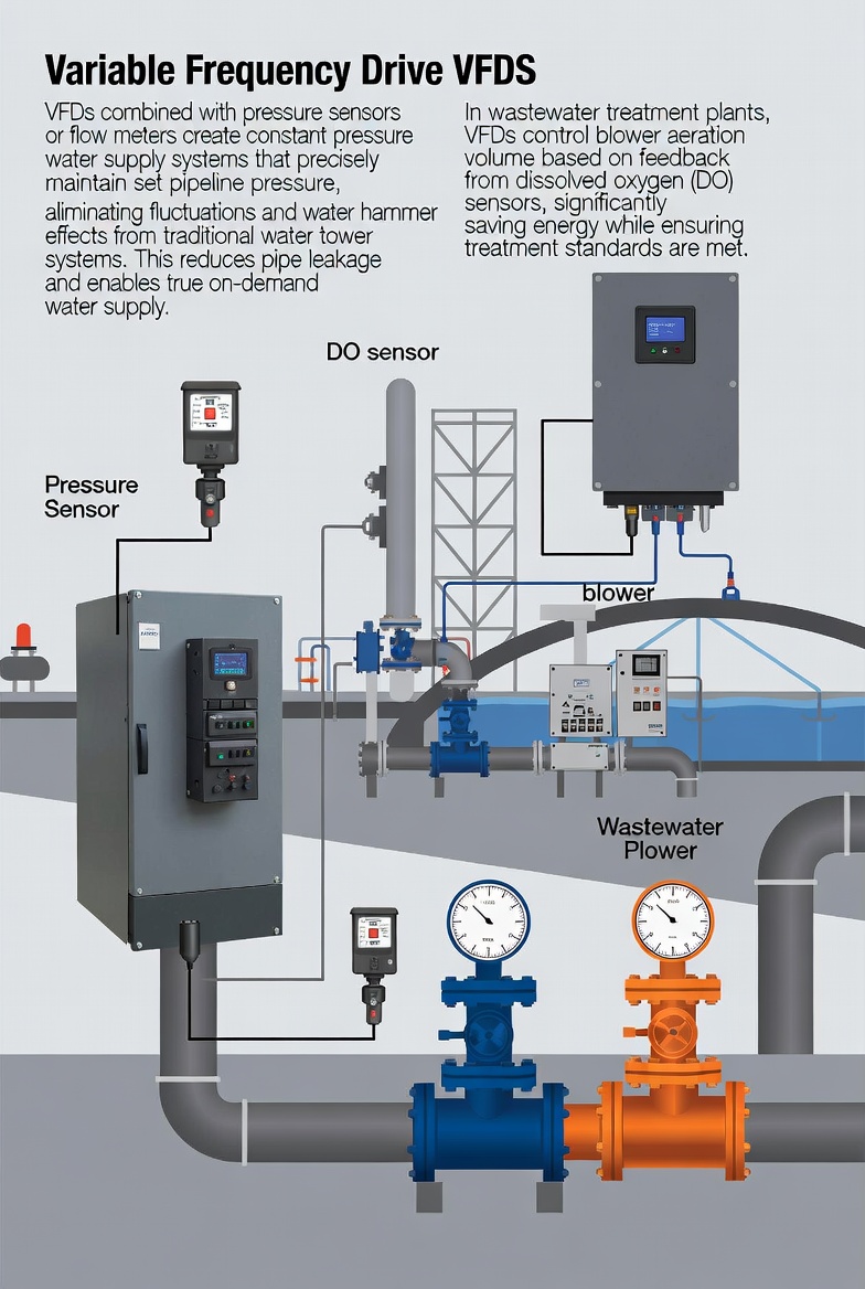
8.3 Water Utilities and Water Treatment Industries
When paired with pressure sensors (or flow meters), VFDs form variable-frequency constant-pressure water supply systems capable of precisely regulating pipeline network pressure to a setpoint. This eliminates the pressure fluctuations and "water hammer" shocks inherent in traditional water tower storage systems, reduces pipeline leakage rates, and enables truly "on-demand" water supply. In wastewater treatment plants, VFDs are utilized to control the airflow of blowers (based on feedback from Dissolved Oxygen [DO] sensors), thereby significantly reducing energy consumption for aeration while ensuring that treatment standards are met.
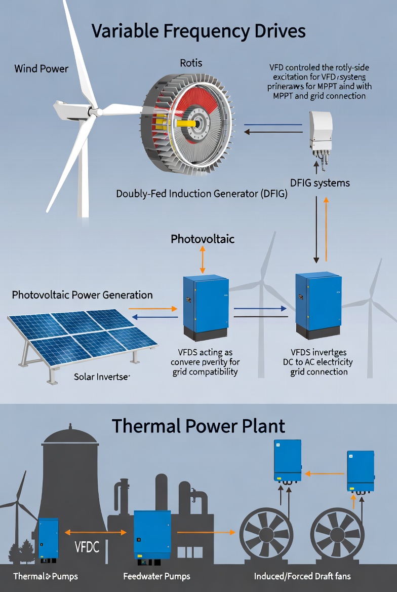
8.4 New Energy and Power Industries
In the field of wind power generation, VFDs within Doubly Fed Induction Generator (DFIG) systems are used to control rotor-side excitation, enabling Maximum Power Point Tracking (MPPT) and grid synchronization. In photovoltaic (solar) power systems, VFDs—acting as inverters—convert direct current (DC) into alternating current (AC) that meets the specific frequency requirements of the power grid. Furthermore, applying variable-frequency speed control to high-power auxiliary equipment in thermal power plants—such as boiler feed pumps, induced draft fans, and forced draft fans—represents a key strategic direction for energy conservation and consumption reduction within the thermal power industry.
IX. Electromagnetic Compatibility (EMC) and Harmonic Mitigation
During operation, VFDs generate two primary types of electromagnetic interference (EMI) issues: first, low-order harmonic currents (e.g., 5th, 7th, 11th, 13th harmonics) that are conducted back into the power grid via power lines—resulting from the nonlinear chopping of grid current by the rectifier bridge. These harmonics can distort the grid voltage waveform and disrupt the normal operation of other sensitive equipment within the same power supply system. Second, radiated electromagnetic interference generated by high-frequency switching operations, which may interfere with surrounding communication and control equipment. To address the aforementioned issues, engineering practice typically employs the following technical measures: installing an AC input reactor on the input side of the variable frequency drive (VFD)—which can reduce the total harmonic current distortion (THDi) from approximately 75% to about 35%; for applications with stringent harmonic requirements, utilizing 12-pulse or 24-pulse rectification technology, or deploying Active Power Filters (APF); installing shielded cables for the output connection between the VFD and the motor, accompanied by proper single-point grounding; and installing an EMC filter on the VFD input side to ensure the product complies with EMC standards such as IEC 61800-3 (Class C2/C3).
X. Technical Development Trends and Outlook
Currently, VFD technology is undergoing simultaneous evolution across multiple dimensions. In the realm of power semiconductor devices, third-generation wide-bandgap semiconductors—exemplified by Silicon Carbide (SiC) MOSFETs and Gallium Nitride (GaN) HEMTs—are gradually displacing traditional Si-IGBTs. Leveraging their extremely low switching losses and high-temperature tolerance, these advanced devices boost VFD power density several-fold and elevate efficiency to over 99%. Furthermore, they support higher PWM switching frequencies (>100 kHz), thereby completely eliminating motor operational noise; consequently, the industry regards this development as the next revolutionary leap in VFD technology.
Regarding digitalization and networking, the integration of Industrial Internet of Things (IIoT) technologies has transformed the VFD from a mere speed-control device into an intelligent drive node. Equipped with embedded edge computing capabilities, a new generation of VFDs can collect, process, and upload massive volumes of operational data in real time. This capability facilitates machine-learning-based Predictive Maintenance, enabling early warnings of impending motor or mechanical failures and thereby minimizing unplanned downtime. Concurrently, through seamless integration with Manufacturing Execution Systems (MES), Enterprise Resource Planning (ERP) systems, and cloud-based industrial platforms, these devices enable comprehensive digital management and control of production operations, thereby accelerating the factory's transition toward Industry 4.0 intelligent manufacturing. In the realm of green and sustainable development, regenerative variable frequency drives (VFDs)—equipped with energy feedback capabilities—are poised to find increasingly widespread application in scenarios involving frequent starts and stops, as well as high-inertia loads. Furthermore, modular and standardized VFD design concepts will significantly reduce spare parts management costs for users. Concurrently, high-efficiency VFD systems that meet the IE2 energy efficiency class requirements of the IEC 61800-9 standard (the EcoDesign Directive) are set to become a mandatory market entry threshold in major global markets, thereby driving the entire industry toward higher levels of energy efficiency.
XI. Conclusion
Through a core AC-DC-AC power conversion chain—combined with advanced PWM modulation techniques and high-performance vector/DTC control algorithms—variable frequency drives achieve precise and efficient control over the speed and torque of AC motors. Their comprehensive value across areas such as industrial energy conservation, process optimization, equipment protection, and system intelligence has been fully validated through global engineering practices.
Zhejiang NENA Electric Co., Ltd. remains steadfast in its commitment to technology-driven innovation, continuously integrating the latest power electronics technologies and advanced control theories with the practical application demands of industrial environments. We are dedicated to providing global customers with high-performance, high-reliability, and high-efficiency VFD products, along with comprehensive drive solutions. We look forward to joining hands with our industry partners to collectively advance the frontiers of electric drive technology and contribute to the green transition and high-quality development of the manufacturing sector.
References
[1] Mohan, N., Undeland, T.M., Robbins, W.P. Power Electronics: Converters, Applications, and Design[M]. 3rd ed. John Wiley & Sons, 2003.
[2] Bose, B.K. Modern Power Electronics and AC Drives[M]. Prentice Hall, 2002.
[3] IEC 61800-5-1:2022 Adjustable speed electrical power drive systems – Part 5-1: Safety requirements[S]. International Electrotechnical Commission.
[4] IEC 61800-9-2:2017 Adjustable speed electrical power drive systems – Part 9-2: Ecodesign for power drive systems, motor starters[S]. International Electrotechnical Commission.
[5] Chapman, S.J. Electric Machinery Fundamentals[M]. 5th ed. McGraw-Hill, 2011.
[6] Holmes, D.G., Lipo, T.A. Pulse Width Modulation for Power Converters[M]. IEEE Press, 2003.
[7] Depenbrock, M. Direct self-control (DSC) of inverter-fed induction machine[J]. IEEE Transactions on Power Electronics, 1988, 3(4): 420-429.
[8] European Commission. Directive 2009/125/EC (EcoDesign Directive)[EB/OL]. Official Journal of the European Union, 2009.
 English
 中文简体
中文简体 عربى
عربى


 浙公网安备33038202003754号